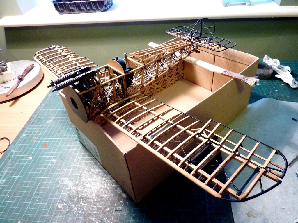
Sopwith Camel F.1 – Upside Down and Back to Front: Undercarriage and Lower Plane

This is the final instalment of the 1:16 Sopwith Camel F1 build sequence. The remaining work is with the main and cabane struts, upper plane and rigging, so the next time I post (all being well) it will be to show the completed project. If you never hear again from me about this project you'll know it went horribly wrong...
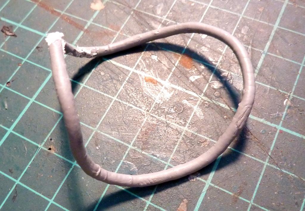
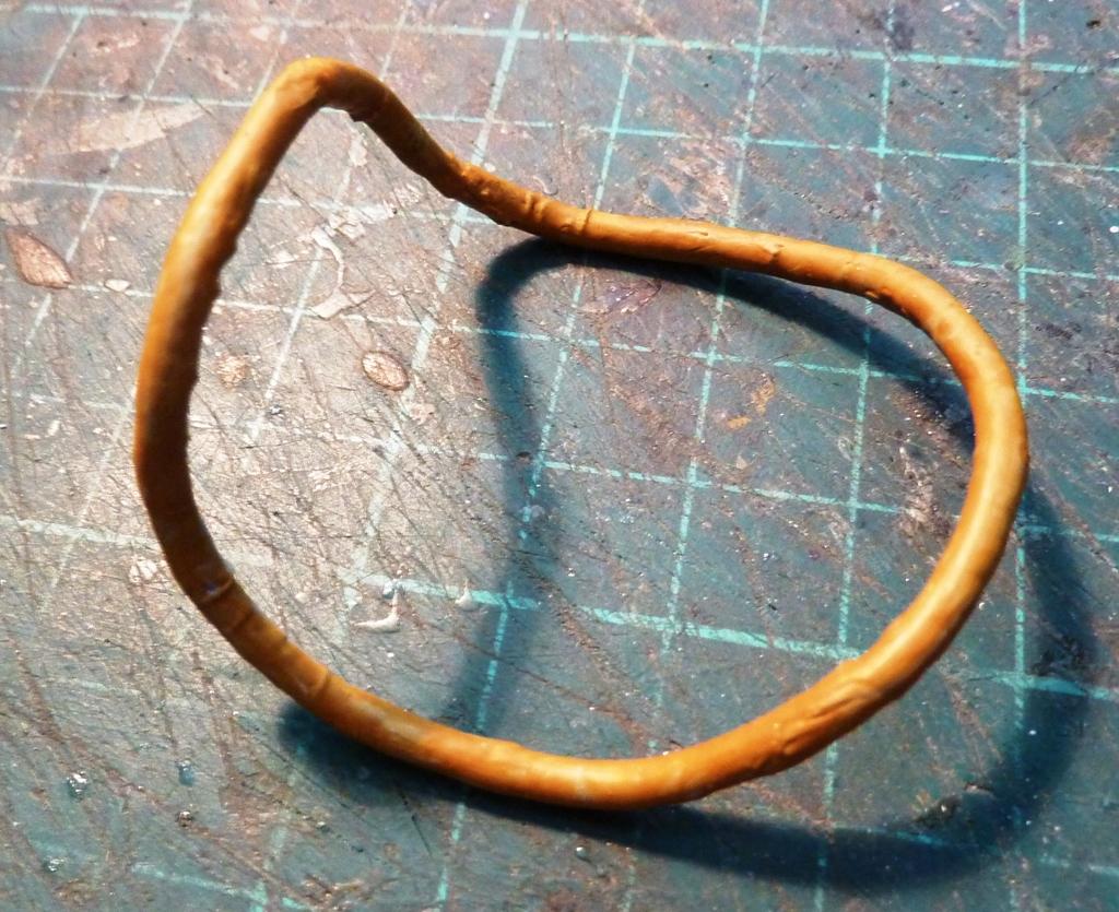
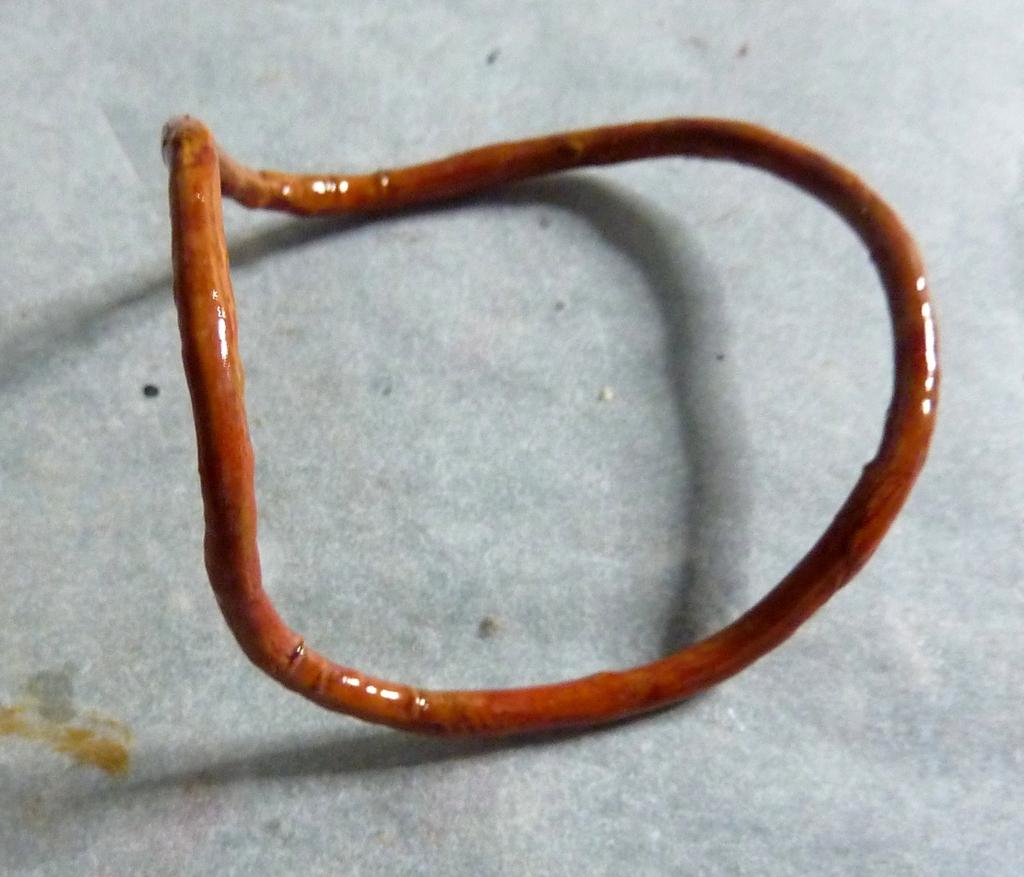
Before I started work on the undercarriage, I decided to complete the cockpit coaming, as I thought there might be issues later after the main plane was installed, with lining up the coaming itself. The coaming material is nothing more than a thick length of copper wire sheathed in plastic insulation. The length was measured and manipulated into what our American friends would call a "potato chip" shape. I used artists' oils to simulate a red-brown leather, and the crinkles in the insulation that resulted from hand-shaping the piece were not unlike worn leather - a simple idea, but effective.
I spent a morning installing the lower wing. There was a deal of fettling involved and I still think it's fractionally out of square. I won't know of any repercussions until I try to settle the top plane into place.
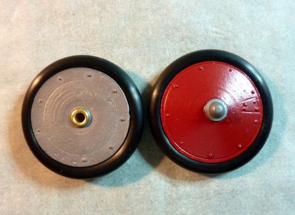
The wheels are a two-part hub assembly with a brass tube inserted through each for strength. The tyres are rubber and not unlike handling a particularly unruly elastic band. The hub halves have no dovetail joint to form a firm mating surface. Instead, the hub rebates receive a discreet dotting-round of gel cyno, with the tyres then centred and sandwiched into place. I ran a mix or water/white glue around the outer faces where the tyre edge met the hub, to seal the joint thoroughly.
The photo here shows the units painted, but prior to matte coat of varnish.
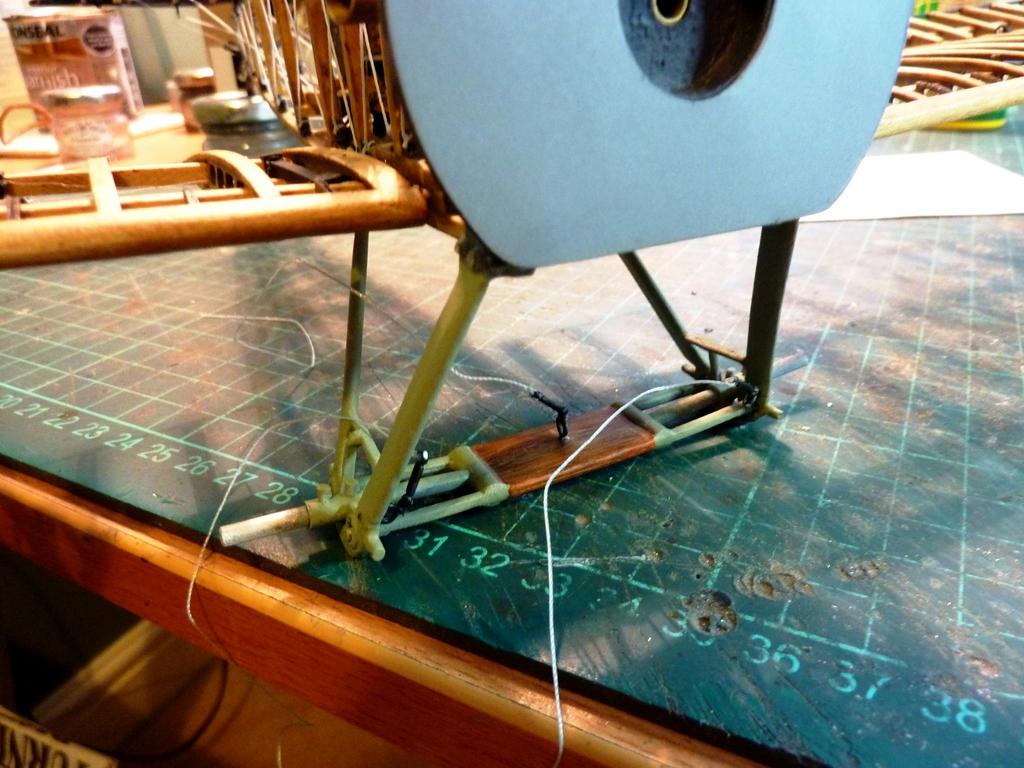
The axle is a chunky single piece of white metal (as are all the undercarriage parts). The upper face shows an open chamber bisected front-to-back with a stiffening bar. There's a pre-drilled guide hole central to this, but the bar itself has to be filed down to the same level as the adjacent metal so the hole has to be re-drilled. The instructions suggest using a piece of aluminium, from a drinks can or similar, to cover the chamber, with enough to wrap over the front and back edges of the axle. A hole is to be drilled in the aluminium directly over the hole in the stiffening bar. However, I used a thin piece of plasticard instead and all was well. The hole, by the way, is simply an anchor point for a turnbuckle.
Here, the centre is wood-grained using artists' oils. The metal surround is painted light green at this point, rather than khaki green, as the latter is too dark for me to see what I was doing in and around other operations in this complex area.

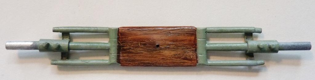
At this point, the axle is married to the struts and brass eyebolts have been installed for current and later operations, where turnbuckles or fairheads are required.
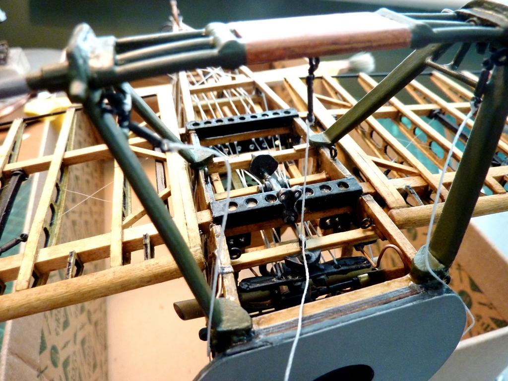
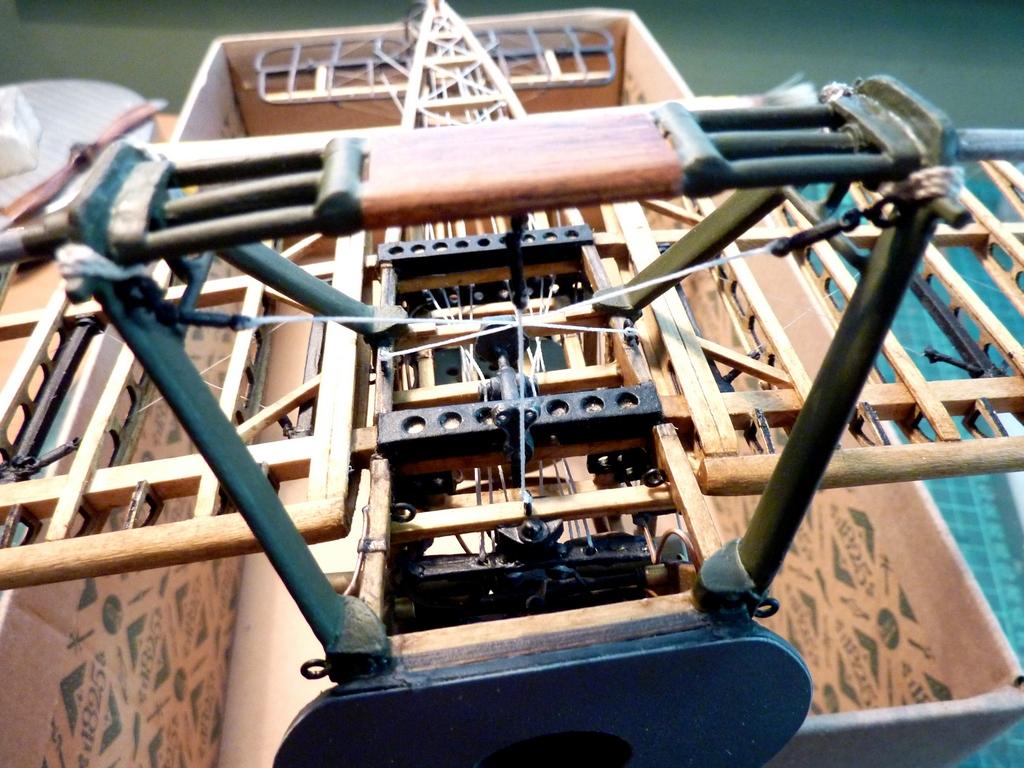
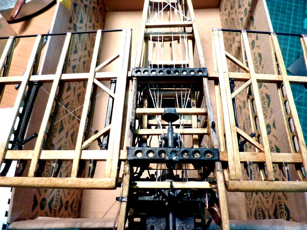
Rigging complete now, with wheels in place, with a detail of the control cabling in view as well, lower cockpit area. The bungee cords around the outside edges have also been installed.
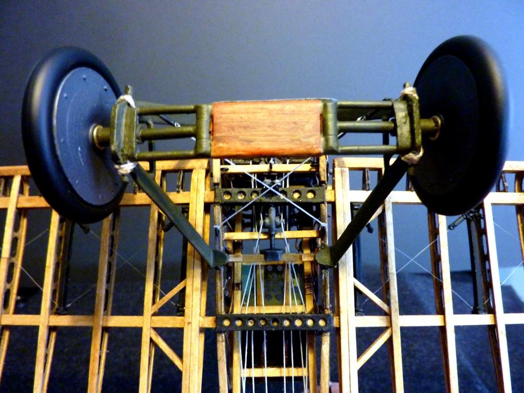
And a couple of shots 'right way up' of the completed unit.


There are only a dozen parts to the undercarriage, including the turnbuckles, but the work took nearly a week to complete.The phrase, "like herding cats" comes to mind.
A true labor of love, Rob...your talents are obviously shining through with this project.
Rob, the amount of detail is stunning & your work is super!
Some of us Americans actually know what a "crisp" shape is, too. 🙂
(I could happily have a big mess of chips with malt vinegar right now, after finishing my last bag of Walker's Tomato Crisps I just had. Yummy!)
Wow - just your work on that small wood-grain panel is extraordinary. They say a helicopter is 30,000 parts flying in formation. Your finished product will be dozens of well-crafted models representing one!