A little background...
The S.M.1 (A3) was developed from 1915 to meet the French military A3 specification, which called for a three-seat long range reconnaissance aircraft with strong defensive armament. The S.M.1 was unconventional, powered by a single liquid-cooled radial engine mounted in the fuselage powering two airscrews mounted between the wings with a system of gears and drive shafts. This layout was chosen by Moineau to minimise drag. The twin airscrew layout allowed a wide field of fire for the two gunner-observers, one seated in the nose and one behind the pilot.
The aircraft was tested in early 1916 and was sufficiently successful for Salmson-Moineau to receive an order for 100 aircraft, although the performance was inferior to the Sopwith 1½ Strutter.
In service the S.M.1 was not successful. The nose-wheel undercarriage would collapse if misused and this caused many accidents. The complicated transmission system was difficult to service in the field and the performance of the aircraft was poor. It appears that around 155 S.M.1s were built in total. The type was largely withdrawn from service in 1917 but a small number of aircraft remained in use until late 1918. Some S.M.1s were supplied to the Imperial Russian Air Service, but they were no better liked in Russia.
This is Copper State Models' fairly unique model of the type. In fact, I'd wager that few people have even heard of it. There aren't that many archive images of the aircraft, even in specialist publications, and I've seen only one completed CSM build on the Internet.
This is a resin kit in 1/48, with additional PE. There are markings for two machines, No. 12 of F58, and No. 125 of Sop43. The finishes are doped linen, metal, and light grey.
There's a very nice range of resin parts, all bagged separately by group type, and everything inside a sturdy cardboard box. All the resin has to be separated from individual casting blocks, and washed in mild soap and water to remove the slip agent.
The instructions don't follow the usual format. They are simply plan and elevation views of the machine, without specific reference to where and how parts should be fitted.
There is a separate sheet that serves as a callout for the PE parts, but it still presents similar location issues. Here are a couple of examples from the PE listing:
(26) These are the parts that attached to the lower wings (see stbd wing and bottom wing detail). Don't know what to call this.
(29) Don't know what to call this. Eric might...(x4). And you have two different sets of parts numbered "29".
It's probably the case that CSM sent a prototype kit to someone to test build and these are some of his notes, transferred directly to the listing. A little amusing, yes, unless you're actually trying to build the kit.
To give CSM their due, they do state that "due to some technical difficulties and temporary lack of experience on our side, instead of publishing full building notes here we have published some assembly notes on our website." It's true, they have, but it’s simply a series of photos at completed build stages, and with no PE detailing shown at all.
Well, I like a challenge.
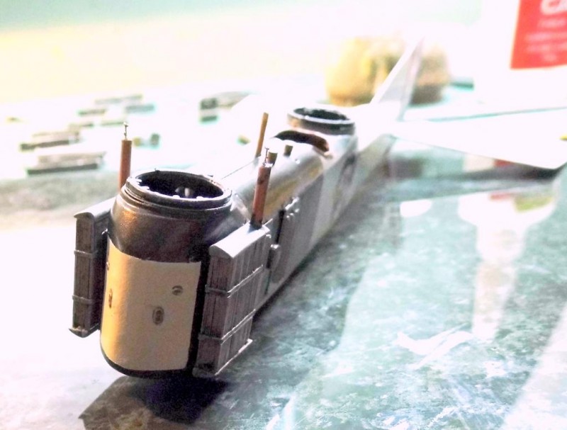
The kit's unusual engine is seen facing outward at an opening in the starboard fuselage (bet you never saw that coming). The engine itself is beautiful - about 60 parts, mostly resin, but with a few PE rocker arms. The modeller has to add the push rods (mine are 0.02 metal rod) and I added ignition wiring using a fine grade of lead wire painted pale yellow.
It's unfortunate, but the usual thing, that so much detail will be lost inside the fuselage, but here are a few photos of the engine progress to give you some idea of the excellent detail.
Got to say, it looks the business.
And speaking of the fuselage, here it is.
Now I just have to figure out which of the dozens of resin bits go where.
...A little further on, with difficulty.
Having researched the Salmson 9 engine a little more, I decided that I had part of the engine painted the wrong colour. An easy mistake, as there were different versions of the engine, as it was developed. I painted the piston heads black, correct for this version I believe, but some models had the heads encased in copper. Also, I'd read that the circular section outward-facing was an off-white; I just can't see this as correct, and so have repainted this. I removed the vent pipe later when trying to get the fuselage sections sorted (more anon).
There are double vents to the engine compartments on the port side. These are nicely depicted in PE, but I wanted them to look nestled-in to the side of the fuselage and so taped the edges of the areas and carefully abraded the face of the resin to take it down a mil or two.
The floors, sidewalls (in part) and the bulkheads were finished in timber. I remembered I had a surplus section of wood laminate used for WW2 ship's decking, and so cut the sections to fit. The wood was stained and sealed with a matt varnish.
There's a nice resin pilot's seat, as well as a PE version; I used the resin.
I took the opportunity to add a little detail in the forward observer's area. I made a little Morse key from PE spares, and a few other wireless-related bits. The antenna reel is made up from watch spares, with a little lead wire wound around, although it can't be seen much when the area is enclosed.
The next photos here are the completed areas. I should add here that the seatbelts are spares I had, by Eduard, as there are none in the kit. The rudder bar and adjacent areas are all from plastic stock. The only kit item is a PE steering wheel, to which I've added a small section of terrain map, also from spares.
The next image is of the instrument panel. The clear sections have just had a drop of Glue 'n Glaze and are still a little opaque, as not completely dry.
This was an unpleasant task. Usually, the manufacturer would supply a backing piece in PE or plastic (or resin, in this case). The dial faces would be a complete layout on acetate and you simply paint the back of it white to 'pop' the printed black details. This is then affixed to the rear of the instrument panel, often now in PE, and the until is glued to the backing piece. There are of course various permutations.
In this case, the bezels were part of a PE fret, but each was separate on the fret. Ditto the dial faces, which are tiny and have to be cut from the thick acetate individually, and then fixed behind the bezels. What a pain, and doubly so when you consider that most of the work is out of sight under the coaming.
As you can see here, most of the main sections of the fuselage are together, but in fact the fit was a struggle. Various surgery tasks were necessary to get the parts together, and the coaming over the top - not yet in place as a few interior details were being finished - had to be reduced in length. When butted to the rear top infill, the forward coaming overshot the front of the observer's area by 10mm. In the course of this, I discovered that these differences affected the position of the pilot's seat, and other items, which had to be repositioned.
So, a bit of filling and sanding to do to get this where it should be. I'm setting it aside a few days to get my head around where I am with this. It's one of those builds where a small adjustment at one stage, which looks innocuous in many respects, may have more serious consequences further on.
...
And so it came to pass.
The suspected fuselage issues arrived with a bang. Despite having set the side sections into the rebated base piece so that everything appeared to be in place, I built a banana.
I think it was something to do with having to remove the circular section in the right hand piece (CSM has helpfully scribed the area as a circle.), effectively making it into two pieces. The space created is where the engine face appears. There's also a PE circle that defines the outline of the area, which is nice, but in the end it was just another thing to have to deal with.
I said previously that I had only seen one of these models finished and posted online. Since then, I discovered a second build by a Russian chap, Sergey, from early 2016. He seems to have taken the kit to the top wing-set stage, but there's nothing after that. Not sure if he gave up, or completed it sometime in the past two-and-a-half-years and simply never did a follow-up post. When you consider that only 350 were issued, and only one-and-a-bit kits are completed, there's a message beginning to emerge...
To rectify the problems that arose here, I faced the rear fuselage areas with a thin card, plus required filler, until I lost most of the banana shape, although there is still a little twist to the rear fuselage, but nothing like it was.
Here's what it looked like, from the first passes to more finished work.
I then remembered that there was no kit slot provided for the tailplane, and so had to measure from the plans and cut the aperture.
So, after a number of face-filling exercises using finer and finer filler and sanding sticks, I was ready to prime one final time (Previously, after each fill the primer was applied to show up any indiscretions; this went on for some time.)
The eagle-eyed amongst you may notice my finely finished engine is now back to 'square one.' I found, too, that on the PE fret there was a small triangular piece, marked mysteriously, 'engine cover'. I think it's meant to be placed over the ignition wire boss against weather. In any case, I sprayed it Steel and set it accordingly.
Apart from repainting the engine, the rest of the fuselage had to be finished, too.
I used the AK Interactive CDL set for the fuselage and empennage. For the tailplane, I first used a lighter, bleached version overall, then masked the rib tapes with strips of Tamiya tape, and followed on with the darker version overall, which, upon removing the Tamiya strips reveals the rib tapes in a lighter shade than the surrounding areas. Pretty basic, but looks fine in 1/48.
The front of the unit around the forward crew area and engine cowling is in metal, a mix of AK Bronze and Steel. I should probably have favoured the Steel a little more in the mix in hindsight. CSM recommends the metal areas to be painted grey, but there's so much 'up in the air' with callouts for the kit, I went my own way with this one, although I did finish the rear areas of the upper cowling in grey.
I mentioned previously that there were two decal choices. One you see below. A second utilised the numeral "5" but gave to indication as to the position of the larger numerals presumably to be used on the top wing somewhere, so I avoided that choice. However, there was in fact a third option, which showed a cockerel's head, probably to be positioned on the sides of the fuselage, but no instructions for these so they were also set aside.
The scarf rings have a PE circular base on which is set a nicely detailed resin piece. Further detailing for the gun supports will follow later (no guns supplied in the kit).
The vent stacks for the radiators are shown on the plans, and at first I thought they were missing as I could find nothing in the kit so I made up a couple from plastic rod and added a little lead wire for the pipes, painted Copper, running from the rads into the fuselage. I later found that the ‘missing’ elements were in the bag with all the struts. By now of course my scratch items were fitted and I think look better, with more detail, but nothing wrong per se with kit items 9.
I've also added the kit's PE control horns and control line grommets. There are still ladders and the tail skid to add, but they're too delicate to chance installation at present.
Considering the complete hassle I've had, I think I've beat it into submission now and can move on. I noticed after setting the tailplane that although it looked square when viewed from the rear, looking aft from the front it was skewed - another banana-build legacy. I used a scalpel to remove the planes where they met the fuselage sides, and reset them in a butt joint either side so that looking aft they appear correct in a left/right balance. They don't look right when viewed from aft forward (anhedral), but the aircraft sits very low on its skid, and so there will likely never be an opportunity to see the issue.
The unit has had a thin coat of Future brushed overall, to seal the decals and keep the paint work clean (hence the shine), so I still have to give everything a light spray of Matte or Satin varnish to settle it down.
Onwards!
...
A short update, as I'm finding that each part of the build seeps into everything adjacent and affects progress. Firstly though, after completing the fuselage, or nearly so, I realised that the nose of the crew area should be in CDL and not a metal finish, so I had to carefully mask around the radiators, etc., and spray it out on the CDL I'd used elsewhere.
-
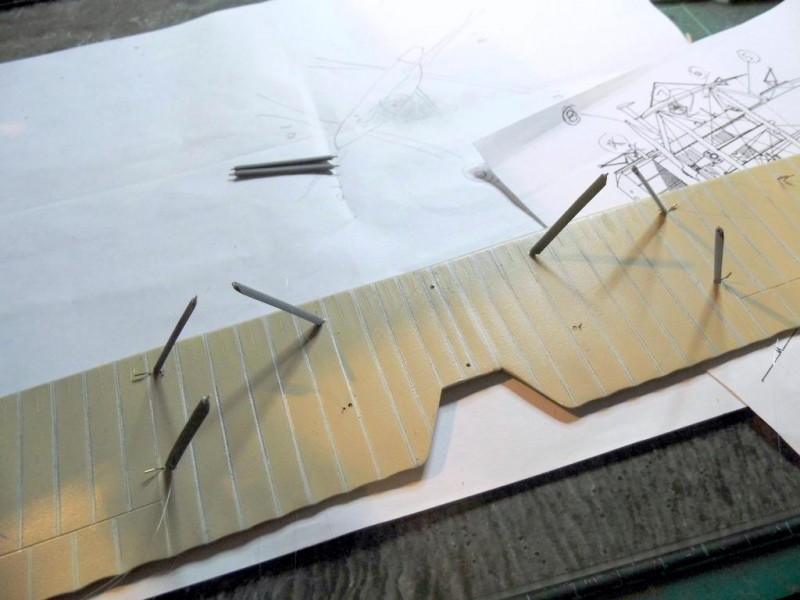
There are loads of struts and other connecting pieces in various lengths. A number of them are helpfully hand-scribed with numbers on the casting blocks; others have nothing. Unfortunately, there are no numeric references whatsoever on the plans. I've separated the same-numbered pieces into respective groups, and then will have to measure from the plans to ascertain the correct locations. A few, like the four main struts, are straight-forward, but there are others that sit at odd angles in odd places that will require study. I think too that I may have to replace a number of the resin locating pins with wire. I can't see some of these pieces withstanding the substantial weight of the large resin wings and fuselage combined (This is a large kit, more like 1/32.)
I've primed and painted the aforementioned numbered pieces and brushed on a single coat of Vallejo Neutral Grey, ready for the next stages.
Before any of the above can move forward, the lower wing need to be completed. Here, the wing has been primed and sprayed with AK Bleached Linen CDL, after which I've masked the rib taped areas and then over-sprayed all with a darker CDL. When the masks are removed a contrast is achieved. It's the same process as on the tailplane, but here the rib tapes themselves are scribed into the face of the wing, which gives a more realistic look. Further, before the masking is removed I've rubbed a little graphite powder along the rib tapes length-wise, to create a shadow effects once the masking strips are removed.
Here, the (PE) reinforcements have been added, in Steel colour, along with the fuel tank, in grey. I've also added fuel lines from a fine lead wire, paint in a dark tan colour. There's a bit on the plans for this, but without noting what it actually is. I can't see it can be anything other than fuel supply so I've gone with that.
The underside is similarly configured, and the roundels are in place. I still need to seal them and run a little graphite powder over them to tone them down.
The gaps in the wings are where undercarriage sections are built up. They'll need replacing in part with steel wire. Tricky.
...
Another quick update. I've decided to keep them short and sweet to help me remember where I am with things, as the model is getting quite complicated.
One last look at the roundel on the underside of the lower wing. You can see that a little graphite powder 'pops' the rib tapes beneath.
I've separated the various individual struts now, properly, having replaced all the resin locating tabs with wire. I used 15 amp fuse wire as it's fairly strong but will bend a little, too.
One thing I noticed was with strut 6, which is shown on the plans as one of the cabane struts, as far as I could tell; I only had one, and I know I hadn't lost any. The plans, as far as I can see, would have two in place, so I've made one from plastic stock. The wire tails will be trimmed later.
The plans, frankly, aren't much help trying to decipher which strut goes where.
(POSTSCRIPT: having had a moan about this, and “corrected” for the supposedly missing item, I’ve just made out on the plans that there is one short centrally located cabane strut, just in front of the pilot’s windscreen, and two sets of longer struts angling from the fuselage outward to points at the tops of the “X” supports in two separate locations, respectively. When seen from the elevation plan this isn’t apparent at all. Nonetheless, this indicates that the single piece is correct. I’ve further noticed that in the previously noted complete build of this kit that no cabanes are in evidence at all, and no PE appears to have been available for the build at the time it seems. So, unknown territory here.)
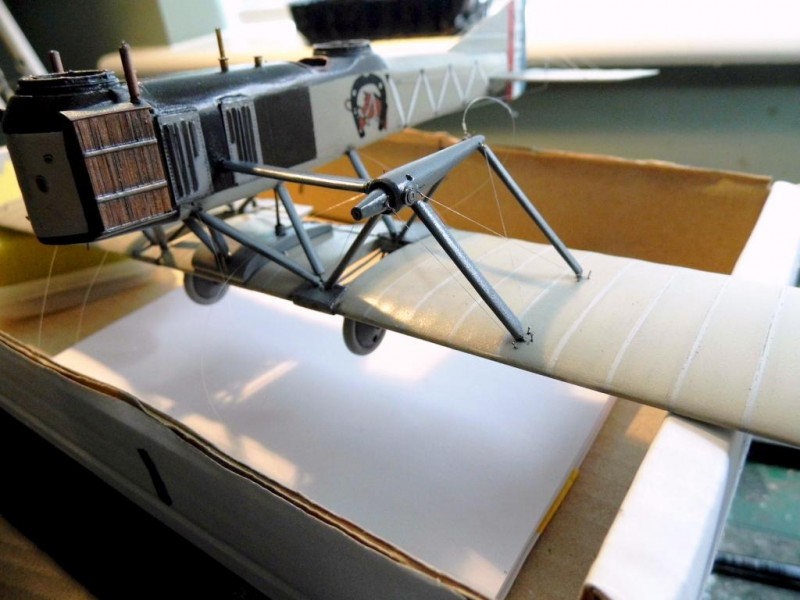
Through trial and error I managed to get the correct struts and complete the complex 'dropped wing' effect, with three struts obtruding at odd angles from the lower fuselage edge, at each side, into the lower wing. You can just see, too, the fuel line from the tank running up into the engine bay. I set two struts either side to stabilise things, then added the fuel line. I could then set the third (middle) strut.
I first thought that a couple of the shorter struts (4) were part of the undercarriage but then saw that the u/c supports had the strut molded with a rod element as a single piece, so the number 4 struts still had to find a home. I then saw on the front view of an elevation plan two short struts rising at an angle from the top of the fuel tank into the forward under-fuselage.
You may think that all this should be self-evident, but deciphering this set-up is a complex job, particularly when trying to match (part) numbered items to plan and elevation views.
The oblong gear housings are supported by four struts to the lower wing and four others to the top wing, thus forming an 'X' shape when viewed from the front. These are struts 10 (x 8) and 11 (x 8), but the plan doesn't show how they're configured, by type, that is. I measured from the plans, and it looks like those that are longer are on the bottom with the others on top, but when I did a test, the gear housing was slanting downward towards the trailing edge of the wing, and I know it should be a straight horizontal line (as seen against the side of the fuselage). I've now switched the lower two rear struts to the longer size to raise the rear housing to the right line, hopefully. If it's wrong I won't know until I try to set the top wing. Great.
The longer units to the rear make sense, when you think that the wing effectively drops away with the taper of the trailing edge. We'll see.
I'm at the point now where I need to get the top wing ready. It's a big wing, in two halves. I've pinned the sections with brass tube for strength.
I've mentioned the elaborate scarf rings and the selection of machine gun supports, but the kit has no guns. I read that armament was some sort of cannon, which I thought was odd, the more so when I checked an external reference and saw the size of these. This aircraft was designed for three people, but the engine performance was so poor they usually only flew with two crew.The idea that they carried cannon was ludicrous. I found at least one image that showed the machine with Vickers armament and so went to order two of these from CSM, but both types they carry were out of stock. I found them at Gaspatch instead.
Nice.
Next stages are to complete the painting and decals to the top wing. I've also drilled a few locating holes for rigging eyelets, in the gear housings, the fuselage and some areas of the top wing. The plans aren't very clear, but I think I know what's going on now, so will set all these things ready for that work to begin shortly. There are no holes in the wings for the four main struts so I'll have to measure from the plans to get the locations.
...
The top wing has been brought forward with the same techniques used for the lower wing. I'm waiting for it to dry thoroughly overnight to then rub it down with micromesh paper and apply the roundels.
I decided that the main undercarriage had to be installed at this point, as I wasn't sure what issues might arise later, with the top wing in place.
I replaced some of the support sections with steel rod, and used the same to shore-up against parts of the resin, for strength. A small piece of rod is set as an axle in each wheel as well.
The rigging to these areas was also completed. I should add that the forward wheel at the front is also complete, with its framework, but it will be much later before I install it. There are two stabilising arms running from either side of the wheel, back to the lower wing. Nothing on the kit for it, so assume I'll use steel rod again for both stability and scale.
The two spinners are now complete. To affect the mahogany finish I used Vallejo Woodgrain with a drop or red dye. The PE bosses are set on both front and back of the spinners, and are well detailed.
I think the next steps will be to complete the preliminary rigging to the underside of the top wing, and to the areas around the gear housing and fuselage.
...
The top wing completed now, with the roundels, and a dusting of Satin Varnish.
At this time it's important to consider what processes might get in the way of other processes, in terms of having to reach over finished work to complete a new part of the project. The empennage is an area that stands alone in some respects, but can cause handling issues as the latter part of the build progresses. Its rigging consists of three control lines from the sides of the fuselage, running back to the rudder and tail planes, and three support lines running across the top edge of the rudder into locations on the tail planes. The areas had been prepped for rigging previously, and so I decided to finish off the finer points of the area.
The tail skid isn't provided as a resin piece, rather, as a PE section, flat-profiled and delicate. As you can see, it's well-engineered but pointless in terms of the task at hand, that is, to support a great weight of resin. It may as well have been a piece of cotton thread for all the support it would provide. To remedy the issue, I cut sections of steel rod and set them against the PE section.
And here's the empennage completed.
The next immediate task is to set the rigging eyelets for remaining areas.
...
And here we go.
I've set the eyelet sprigs in their respective locations on the lower wing, the fuselage and the gear nacelles.
A few of these will be rigged eyelet-to-eyelet, that is, without using the 2mm tube sections. The reason is that some sections of rigging appear to be a discreet cable that all but disappears into the wing/fuselage fabric, and others look a little more structural; for these latter items the tube sections will be threaded on the rigging lines in front of the eyelet aperture to give that extra length.
In the case of the photos above, everything is an eyelet-only contact at present. When the top wing is sprigged and rigged and the top wing in place, I should simply pull through the loose end of rigging through the eyelets on the lower wing or thread the tube into place to mirror those areas so-rigged on the upper wing.
There are traces of cyno here from the work at hand but these will be dealt with later; nothing looks good magnified 20x.
Here's part of the upper wing with its sample rigging combinations.
I previously mentioned the "X" shaped supports for the nacelles and that the top set (4 struts) to each nacelle had to be dealt with once all other adjacent items were in place. This includes the rigging to the underside of the top wing (effectively unreachable once in place) and the eyelet rigging that creates its own mini "X" shapes on either side of each nacelle in both the lower and upper areas. I have to rig the lower sets as complete as I won't get access to them once the upper wing is in place. The eyelets for the upper units will be set, with the completed rigging from the upper wing drawn down to these areas as described.
-
-
The control horns (PE) have to be addressed, too. The connecting rigging that runs through the wing to upper/lower horns is set in place simply by drilling a tiny hole through the wing at these points, setting the underside horn in place each side and securing the line in each hole with cyno so that it stays in place. The line is then fed through the lower horn's rigging aperture, glued, and any excess line trimmed away. The upper horn visible on the top wing will be completed once the top wing is secured.
My concern at the moment is that having completed all this delicate rigging work I then find the remaining struts don't fit, which means the top wing won't fit, which means that the rigging points are all wrong. Unfortunately, the preliminary rigging all has to be completed prior to fitting the top wing.
...
I've been planning things around this next function for some time now. You often hear of modellers who are interested in modelling First World War aircraft subjects, but are put off by (1) rigging and (2) setting the top wing.
The first element is a methodical process, not without issues, but a logical sequence of skills that can be applied to any subject, with appropriate modifications, e.g., double runs of rigging, and so forth.
The second item does in fact differ from subject to subject, not from the fact that for a biplane the wing has to be set, regardless, but in the complexity and number of struts to which the wing will be fixed.
When this kit was released in 2014, I understand that a cardboard jig was included, or at least available from the CSM website, to assist in the top wing set-process. Nothing in the kit now, nor on the website that I can see, but I tend not to use these anyway as I like to look at the model from different angles while I'm doing the work, and a fixed-point set up doesn't seem to suit me. I've seen too that some people use Lego bricks to make up a jig, and these work well, if that's your inclination.
Usually, I first get the cabane struts in place (These are the ones set into the top front of the fuselage, between the spinner and the pilot.) These provide a sound platform on which to set the top wing yet still are few in number and therefore easier to manage, and because the outboard sections of the wing remain 'loose' there are a few squaring adjustments that can be made fairly easily. After that, I add the main inter-plane struts, working outward from the fuselage on either side.
In this case, there were no cabane struts to speak of, only a couple of short vertical pieces. The top 8 struts of the "X" served to stablize things. And in setting the top wing here, I have to say there were a few issues, which I'll touch on shortly, but they were mostly those that I'd expected because of previous "confrontations" with this project.
I've described previously the "X" arrangement of nacelle supports. The lower sets of 4 (each side) were a little tricky, but access was good and of course there was no weight on top of them to disrupt the process. In setting the top wing, I decided to affix the front 2 top sets for each nacelle directly into the upper wing, making adjustments for the width of the nacelle as they tapered down. I also added just one of the rear struts each side. These rear struts could be left wedged (not glued yet) into the rear of the nacelle just to provide support while I was setting the front struts in place with cyno.
-
After a little test fitting, the final process was started, and completed, in a short time. I couldn't believe it. All the measuring and remeasuring had paid off. I mentioned in an earlier update that I wouldn't know if my choice of "X" struts according to length was correct until I reached this point; it was. The forward, shorter struts set spot-on, and though the rear 4 all had to be trimmed just a little, the wing was square and level. At this point there was a short pause while I danced around the room...
Next came the four main struts. There were set holes in the lower wing to position these, but nothing in the top wing, so I'd previously measured from the plans to mark the required holes. When I set the struts, however, the top fit was out of square, so I had to remove the rigging that I'd completed to these areas, and reset the tops of the struts about 5mm outboard from the previous setting. I went back and looked at the plan, and double-checked the measurements, and what I'd done originally looked correct, but clearly not. Anyway, they were corrected and I'll now have to rework the rigging anchors. I managed to salvage 4 of the 8, so not too bad, I guess.
I then set the two short struts that are positioned along the median line of the top of the fuselage, one just in front of the windscreen position and the second just a little forward of that. They both had to be reduced in length.
The two struts that run from the top rear innermost "X" strut, down at an oblique angle to just behind the pilot's area, into the cowling there, are too long. A little test fitting did the trick. These are struts listed as No 5, by the way.
This leaves two final struts, also obliquely set, in the cowling from just behind the forward observer's area outward and back to the top FORWARD "X" strut. The choice of remaining kit struts didn't fit (all too short). I scratched what I needed from styrene, which only took a few minutes.
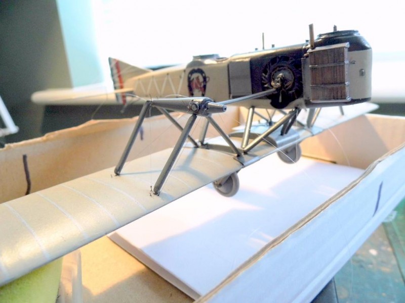
Here's where we are.
Now, with a little touching up to do, I call that a useful few hours' work, all in. In the next day or so I hope to have all the remaining rigging completed, now that the structural issues seem to be resolved. The rigging won't be as straight-forward as I'd hoped because of the issues mentioned above, but it's all manageable.
But before I settle into the rigging again, I thought I'd take a break and sort out a couple of items that will come into play soon, and get them ready.
The first is the pilot's windscreen. It's PE, but there's no acetate in the kit, but as the screen profile is quite narrow, I've used Glue 'n Glaze to infill the area. It dries crystal clear, but I'll still touch-in a drop of Future as a hard shell finish, with a little Steel brushed around the frame.
The other items are the (kit supplied) gun mounts that are fixed atop the scarf rings. They're resin and so delicate the infills between the framework had to be drilled with a minuscule drill bit and then opened up with a scalpel. Amazingly, nothing broke! The little triangular supports for these items are also available on the PE fret. Not sure which version to use; they both have nice details for what they are.
...
Now, after several hours' work, 99% of the rigging is complete. All that remains are the runs across the top of the upper wing that are linked to 2 over-wing structural supports, and two sections linked to the forward wheel.
Next, various paint items to touch-up around the rigging areas, and the various small items to add.
...
The front wheel has been added now, and rigged. No photos of it as it’s a fairly straightforward process, the individual parts having been prepped previously and, as a bonus, the plans actually reflect what’s required! Also completed are the top wing structural supports and rigging, etc. Again, straightforward work, so no additional photos.
Kits like this are far, far, removed from Wingnut Wings or similar (and of course, the scale is different!). You can’t assume anything and have to work that much harder to push the standard.
Quarter-scale modelling is tough (hence the growing popularity of 1/32 biplane kits). One of the benefits of course is that these 1/48 kits generally are inexpensive. A very nice biplane kit in this scale can be had for £25-30. Compare this to other “modern” kits that retail for £100+ and you can see the benefits.
That said, this kit cost about £85, but it’s a complex, short-run resin kit with additional PE. Additional costs have been the rigging eyelets and tubes from Bob’s Buckles (other choices are available).
I mentioned earlier in this thread that I’d only seen two other builds of this subject. One, while complete in itself, had no PE; I assume the fret wasn’t included in the first batch of the kit two or three years ago. The second build was incomplete for whatever reason.
These subjects are difficult projects, and certainly not for everyone, but I think it’s important that such kits exist for these obscure subjects.