ICM B-26C Invader, 1/48th scale USAF

Started by Chuck A. Villanueva · 102 · 1 year ago
  • Profile Photo
    Chuck A. Villanueva said 2 years, 9 months ago:

    Time to pick up where I left off on the ICM B-26C. Getting closer to getting it ready for paint but still need to finish up with some air frame components.
    Starting at the nose, will install the bomb sight and get it painted.


    The base is painted Interior Green and the devices are black.

    While that sets, will do some putty filling at the back top seam of the nacelles and at the base of the tail. Using Tamiya putty.

    While the putty sets, will start work on the gun control pedestal and components.

    The gunners pedestal, consists of the seat, armor plate, adjustment wheel, gun sight and the periscope which has a view below and topside.
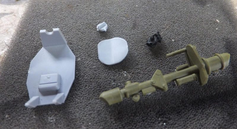
    First the seat is attached to the base of the periscope.

    Then the wheel is attached to side of the scope. Don't know if it turns the electrically power turrets or the scope. Unless the turrets turn with the scope simultaneously.

    Next the armor plate is attached to the scope.

    While using a Ju-188 engine cowling as a base to hold the part while I airbrush interior green to the assembly. Using Nato Black to paint the ends of the scope and Lifecolor Black for the wheel.

    Once the paint sets, I give it a bit of a wash. Silver pencil to show some wear areas.

    Then place the assembly carefully into the gunners compartment.

    The gunners compartment back window is quite clear and the framing well defined when it comes time to mask it off.

    Carefully placing the glass over the gunners scope, it will be loose and able to turn as it is sandwiched between the glass and the lower floor of the gunners compartment.

    The ICM glass fits perfectly in the compartments opening.
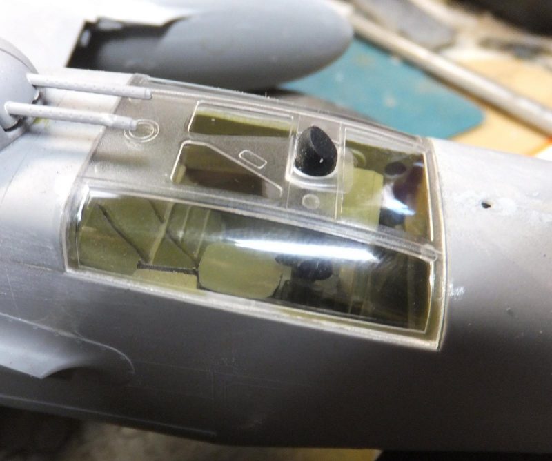
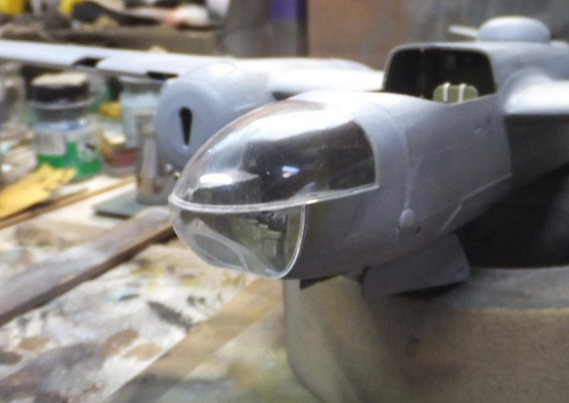
    Now the scariest parts, installing the glass nose. There is very little wiggle room if this does not fit correctly. So hopefully I have everything aligned.
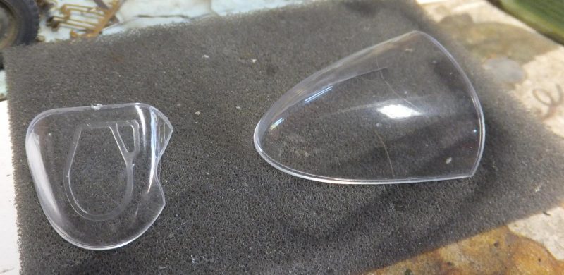
    First I attach the lower nose glass panel. And careful not to get any glue or cement on any of the glass. And not leaving a fingerprint inside the glass. The lower panel fit looks spot on.

    Now the top portion. Looks ok from the top as it meets the forward edge of the nose, no ledge at this point.
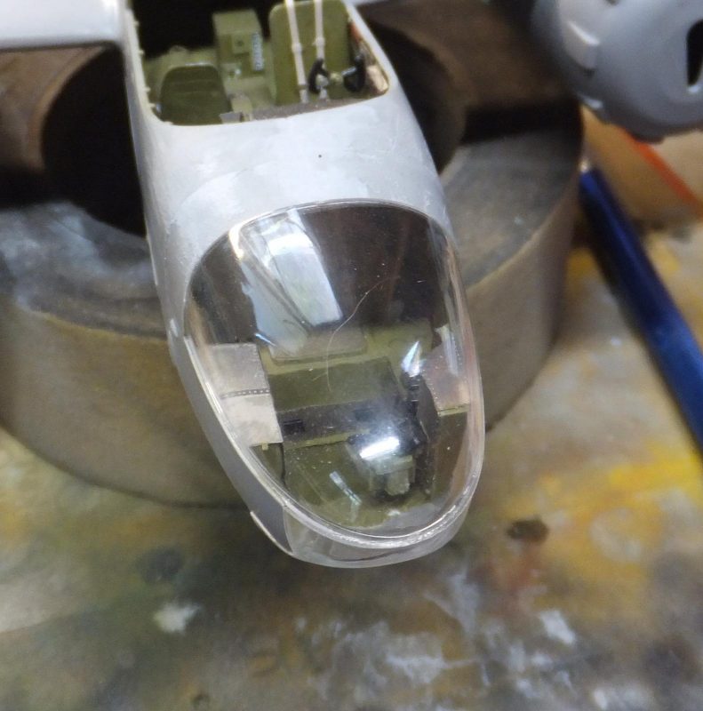
    At the front where the top panel meets the lower glass panel, very tiny gap here, but it does contact the lower panel. The fit is level otherwise, Probably can fill it with Testor's clear cement. The LH side corner fit glass to fuselage is good here as well.

    Next up is to assemble the engines.
    More to follow

  • Profile Photo
    Spiros Pendedekas said 2 years, 9 months ago:

    Great progress, my friend @uscusn!
    Loved the periscope!
    Nice job on the transparencies, as well, especially at the nose!

  • Profile Photo
    Chuck A. Villanueva said 2 years, 9 months ago:

    Thanks Spiros, lot of glass, wouldn't take much if not careful to mess them up. Even now with so much more handling still left to do on this build.
    Next if to assemble what looks like some pretty good looking R2800 radial engines.


    I have already pre painted the cylinders Vallejo Steel over black.

    Then assemble the front and rear halves to build the basic engine.

    Next to carefully remove the pushrods from the sprue. Made easier when you cut the bit of sprue from the main tree and work around the part carefully.

    Next the 2nd row of cyl heads.

    The front side of the 2nd row.

    After carefully removing the push rods from the sprue.

    Then installing the set onto the front face of the engine.

    Then the rear set are installed. Comparing the engines from the Monogram kit, vast difference.

    Now the part of the instructions which goes into Airfix style mode. Where each step is individual parts that go to the engine.

    1st the crank case cover painted Dk Grey.

    Then attached to the engine.

    Another comparison to the Monogram engine.

    Next up are the magnetos.

    What may be the carb,(I should know this)

    The carb is then placed on the center top section of the crank case.

    Then the magnetos are are attached to either side of the carb

    Like the pushrods, the sprue is cut away from the sprue tree to remove it carefully.

    Then attached to the back side of the engine assembly.

    Next the ring is place over the exhaust.

    Now this piece turns out to be a major dumb move on my part in not paying attention. This is really a piece provided by ICM to use as an alignment tool to attach each exhaust manifold. But the instructions to me are vague. Using the visual aid and not reading can lead to a disaster.

    As I place the engine on it like a stand, I glued it on, doh!

    When it should be temporary just simply snap it in place and follow the sequence to install each manifold.

    Which is up next,
    more to follow...


    Next is to install the exhaust collector ring and pipes.

  • Profile Photo
    Erik Gjørup said 2 years, 9 months ago:

    Being a bit behind events here - sorry! Indeed the greenery looks great and clear. Those engines are great little kits in their own and turned out fine. Very nice work Chuck. (isn't the carb the pitch mechanism? or some timing mechanism - the carb/injection would be at the back I think - at least that is the case with the R-1830's I have in the garage)

  • Profile Photo
    Chuck A. Villanueva said 2 years, 8 months ago:

    Hi Eric, they are really quite detailed. But despite the ease of assembly I did get a bit ahead of myself and did not pay attention to one particular major detail I will explain at the next update.
    So now to work on the backside of the engine, the exhaust manifolds and collector.


    The exhaust pipes comes as one piece which you need to carefully remove from the sprue.

    Painted burnt metal. I cut the sprue nubs right at the sprue instead of trying to get the nippers to close to the pipes. Easier to remove by bending them out and then cut them off. And the trim with the knife.

    Once trimmed place the exhaust pipes to the rear part of the engine.

    Next is to install the collector ring.

    Now time to install the exhaust manifolds starting with this part shown

    Going along at this point of the build, there is very little dialog or instructions or which part should be installed first in sequence, it is basically visual. So based on that working on one engine not both at the same time. I see this piece and the image shows to attach it to the back of the exhaust pipes. I didn't notice the "do not cement" icon next to this piece. I just glued it on, This part is a jig to just snap in on the back of the engine, and what it does is help keep each manifold in alignment as you install each one. Now I Know!

    So during this sequence unknowingly that I goofed. I painted the exhaust collector ring rust. And the Interior green.

    Then I follow the directions into inserting each exhaust manifold into place around the manifold jig.

    This is rather ingenious process that ICM came up with and really a great idea.

    The manifolds are painted burnt metal. As each one goes right in place. All in place and in alignment,

    So with that all done. i put everything aside. Thinking to myself that was easy getting those manifolds installed. Let see how the one engine looks with a test fit on the nacelle.

    As you see there is something wrong in Denmark. i look at the image on ICM's instructions. Then look at the engine mounted on the nacelle. Hmmm those manifolds should be in the grooves on the nacelle, why is it sticking out so much? So I rush into the house and start to look at some of the ICM B-26 build reviews, and no one mentions any fit issue or watch out for this in regard to the engines, until a video review step by step detailed review is shown on the installation of the engines. and there it is. He points out this nifty little tool the ICM provides in how to install the manifolds properly using this jig. Aha! So now I know.

    The cooling scoops was another indicator something was not right when test fitting them as well.

    So next will be building the 2nd engine the proper way.

    More to follow. yeeesh!

  • Profile Photo
    Spiros Pendedekas said 2 years, 8 months ago:

    Quite adventurous engine assembly and installation, my friend @uscusn!
    Great result in the end.
    Looking forward to #2 engine!

  • Profile Photo
    Chuck A. Villanueva said 2 years, 7 months ago:

    Thanks Spiros, it has been a learning experience with my first ICM attempt, so getting to know their style of instructions with graphics and very little in a way of reading. Just need to take it step by step.
    Now on to the 2nd engine, but a quick shot of one of the props with yellow tips painted.


    Now to work on the 2nd engine, I won't do a step by step on the 2nd engine as we already did so on the first. However I will once I get to the exhaust section of the assembly. The 2nd time around was much more quicker to assemble. Also have the engine sitting on the exhaust manifold guide plate.

    We are at the point where I'm ready to attach the exhaust collector ring,

    With the collector ring installed, now I can prepare to start the exhaust stacks.

    I use white glue to temporarily attach the rear guide plate. It is a loose fit so this will keep it in place as I attach each exhaust manifold.

    The exhaust manifolds are painted gun metal and also a light rust wash is applied. Each manifold are then placed around the collector ring and exhaust header pipes.

    Once the manifolds are in place and set for about 30 minutes, I carefully remove the guide plate.

    A quick test fit of the cowl over the engine, slips right into place. Where as on the first engine it was rather tight.

    Now that the stacks have dried and sufficiently, a test fit on the nacelle.

    Engine fits perfect, this is how it should look on the nacelle.

    Next up some more wing details to add and mask off the canopies,
    more to follow

  • Profile Photo
    Spiros Pendedekas said 2 years, 7 months ago:

    Those were some nice steps, my friend @uscusn, looks like everything went smooth there!

  • Profile Photo
    Chuck A. Villanueva said 2 years, 7 months ago:

    Yes Spiros, it assembles much more better when you pay a bit more attention to details.

  • Profile Photo
    Chuck A. Villanueva said 2 years, 7 months ago:

    Before getting into the wing flying surfaces. Some house cleaning on the airframe. First to clean the seam around the lower turret insert.


    Next the LH engine view from below. The fit looks good here and test fit each engine cowling which now fit perfectly on both engines.

    Getting closer to the finish after starting both Invaders in June of 2020, definitely long term projects.

    Next to assemble the flaps and ailerons.

    First the outer flaps. ICM have engineered these in a way to hide the seam when assembled. Nice touch.

    To give the Invader some character I will have these slightly dropped.

    Next the inner flaps are assembled. Same bit of engineering here as well.

    The fit here is tight but not a struggle to install.

    Despite the ailerons being long and narrow, they are not warped and installed with no trouble as well.

    Next the rudder is installed.

    Next time to mask off the glass.
    More to follow.

  • Profile Photo
    Spiros Pendedekas said 2 years, 7 months ago:

    Nice steps, my friend @uscusn!
    getting closer to finish indeed.
    Good to see thought after engineering in kit parts design.

  • Profile Photo
    Chuck A. Villanueva said 2 years, 6 months ago:

    Thanks Spiros, now the mundane task of masking...

  • Profile Photo
    Chuck A. Villanueva said 2 years, 6 months ago:

    Getting back to the ICM Invader, masking time. Using Eduard's set for the B-26C

    Starting with the gunners compartment set of glass panels. And the incorrect observers window on the RH side. Incorrect being the shape has the glass being horizontal, when it should be vertical in shape. Size is correct. Also Monogram has the correct configuration as well.

    Always much easier with perfectly shaped masks to cover each glass panel, leaving the framework exposed to paint.

    Next to mask off the canopy, this set has both sets of masks to use for whatever style canopy is used. Which in this case is that later clamshell style.

    Too bad that this type will not have separate hatches to open. And I don't have the patience to cut these open.

    Now the clear nose. Very unique approach on this and excellent as well, to cover the most prominent part of this variant.

    Eduard's provides the maskings to edge the nose panel. Then using Tamiya tape to cover the rest of the inner section of the glass.

    The lower portion also has a nice easy to follow process to mask off the panels leaving the framing exposed.

    Finally to install and mask off the landing lamps.

    Molotow chrome is first applied to the reflectors, then the clear lenses are installed. And masked off.

    Next Interior Green is airbrushed over the framing first before the final finish is applied. First covering the lower nose panel then over the top on the canopy.

    Finally over the rear gunner glass panel.

    Next to install the gun inserts on the wings, final air frame clean up and prepare to paint.

    More to follow.

  • Profile Photo
    Louis Gardner said 2 years, 6 months ago:

    Chuck, @uscusn
    These updates you post are incredibly detailed. Having nice pictures to demonstrate what you are describing is like having icing on a cake...

    You have been very busy, and it's looking VERY nice. Keep it coming my friend !

  • Profile Photo
    Spiros Pendedekas said 2 years, 6 months ago:

    Yep, as our friend Louis said, all look amazing my friend @uscusn!
    Keep it coming!