Thanks, John, Spiros and Erik.
I've been working away at the Buffalo with more stuff coming up to challenge my modeling skills.
Getting this to the painting stage meant attaching and masking the clear parts. Since they are so large and finally restrict access to the cockpit, I decided to scratch-build and install the gunsight beforehand. The Squadron book identifies it as a Mk lll but pics and drawings show it is more a Mk ll, identical to the sight in the Hurricane (pictured).
I figured out the shape as basically easiest to create from a tiny hollowed-out cylinder, cut and sanded to shape. The cylinder came from a silly toy F4U model I got as a "gift" with a Tiger model French armored car (another build in progress).
It was the back end of the "prop" hub.
Other parts of the gunsight were cut or punched from from clear styrene or white styrene sheet.
The rather beautiful pointed oval shape of the reflector glass was reshaped with a file from a more square oval carved with a pin using a template.
-
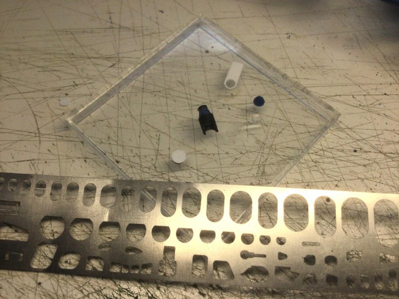
1. Notice how reflector glass had to be filed pointier than original template-cut form.
I feel like a jeweler doing this work with tiny parts but it is kind of fun. I assembled, painted and mounted it before attaching the windscreen but forgot to take a pic of the thing by itself. You can see how it was pretty well centered at this stage.
-
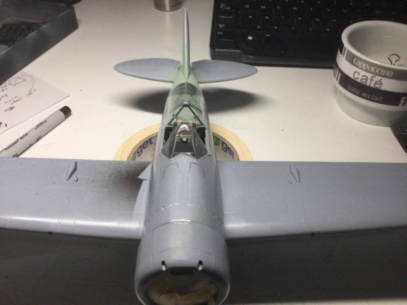
1. Getting the gunsight centered in the windscreen was easier when the clear part was attached.
-
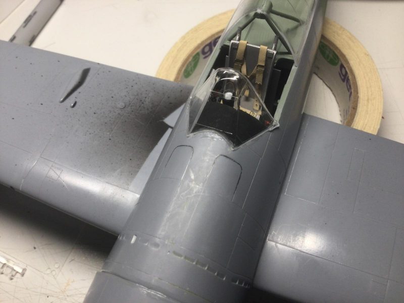
1. I also had to spray the black instrument hood in advance - some tricky masking.
Anyway, the next part was a stage I dread, attaching all clear parts and fairing them into the fuselage without marring them. I used liquid glue because I needed to weld them on and fill some gaps with stretched sprue. I proceeded super carefully and finally got a good join sanded clean for the windscreen.
-
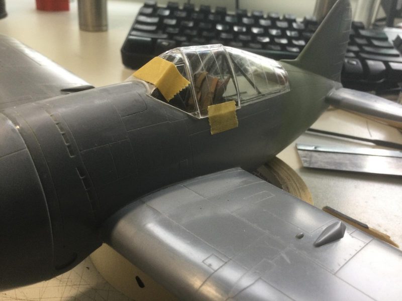
1. Maksing to sand the windscreen join
2. Gap here was fixed with stretche clear sprue
The rear greenhouse part was a heck of a challenge. It needed to flex wider at the base to fit flush with the fuselage and low enough not to leave a step at the back.
-
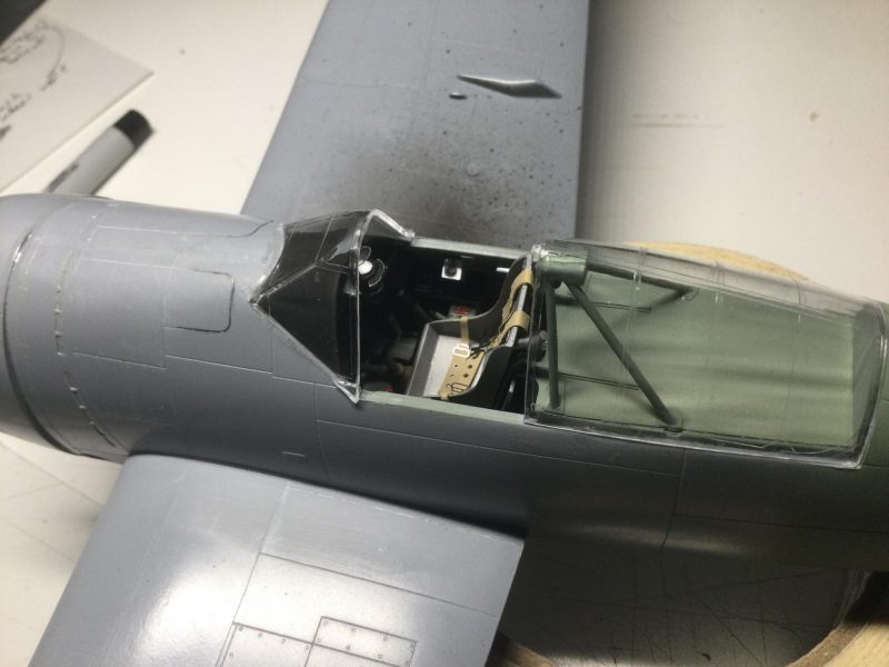
1. Poor fit of green house pretty clear here (much worse on starboard side!)
-
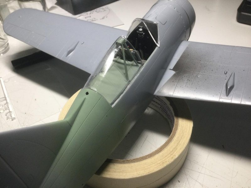
1. I would need to put stretched sprue inside to spread out the clear part to fit better.
-
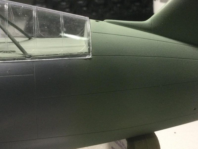
1. Spreading out the clear part also largely fixed this nasty step at the back since the fit became tighter.
Again, I used stretched sprue, this time inside the join to spread the thin flexible part. I used more sprue and Mr. Surfacer outside to close the join and sand it smooth as it is not on a panel line! Meanwhile, I decided to do all the masking to protect clear part panels from sanding and to get that done for painting as well.
The masking was done by pressing the tape into the panel area, marking the major lines with pencil, then removing it to cut it before final placement.
-
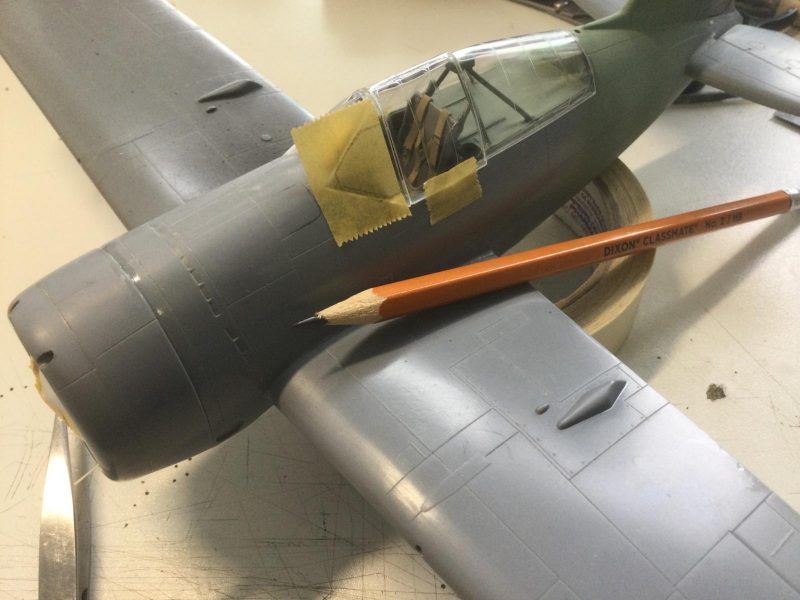
1. cut lines penciled in - tape ws removed for cutting with an Exacto and/or scissors
I NEVER cut it in situ because I don't want to slip and cut the clear part anywhere incorrectly. I hope this is worth showing, even though many modelers know how to do this. I also want to show some other masking details to illustrate how much planning and care is sometimes needed to mask for painting in a build like this. I had the seat and turnover pylon installed, so I had to figure out how to mask around these for painting and ensure no spray would leak inside the cockpit. Putting the canopy on for the whole process was not sufficient protection and its fit would also prevent me from painting the fuselage properly because of the way it overhangs.
The pics show the masking stages and final result and also show how eventually I also faired in the green house canopy piece and scribed the proper line from the fuselage through the clear part.
-
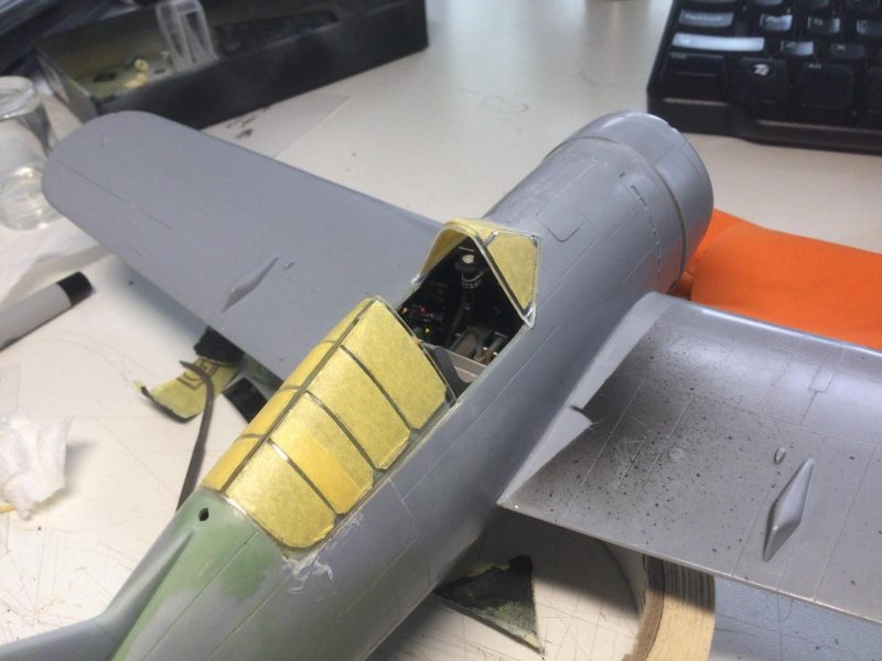
1. Some later application of Mr Surface to clean up the clear part joint here.
-
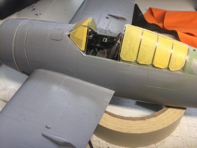
1. Greenhouse is fared in and sanded/polished clear. Panel line as rescribed from fuselage where it is obviously above join line of clear part.
I had to make a box with paper and masking tape around the exposed seat, which I also sealed with white glue in places to stop paint leakage.
-
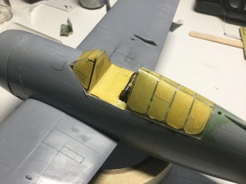
1. Canopy has to be masked open because canopy piece overlaps fuselage here to block painting.
Hopefully the whole thing will resist shrinking and buckling when paint is applied.
BTW, I also had to mask the exposed radial engine after assembly of the cowl. This was tricky, but I hope the paper and tape mask works in the end.
-
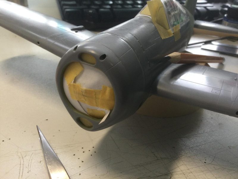
1. Engine masked off for painting.
All along, I have been rescribing panel lines lost to sanding all over the fuselage, cleaning up glue spots and cleaning out sanding dust. more masking challenges await on the underside wheel bay area before painting but I am getting better at this so maybe I can do some major painting next week (?!?).
The last thing to mention is a thing I created to mask the prop hub. It is in two colors, dark earth and sky (not black and sky as the instructions specify). This is pretty obvious in period pics.
-
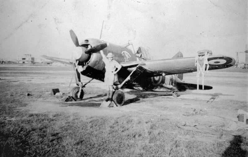
1. Most profiles including those in the Osprey book show the darker color as Dark Earth. You can see in this pic it is not black because of the contrast with the prop.
To overcome the trickiness of masking a straight line on a curved hub, I created the cylinder shaped mask shown. The paper cylinder is wrapped around a marker for the right diameter and symmetry. I lined the inside of the cylinder with double sided scotch tape to which masking tape is stuck to seal the cylinder against paint leakage.
-
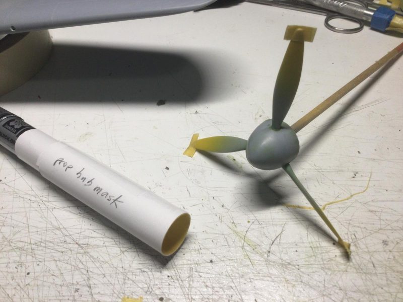
1. Note masking tape inside cylinder to provide a seal against paint leakage in airbrushing.
2. Yellow prop tips have been masked.
-
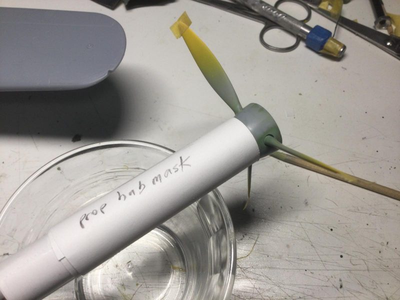
1. Prop hub with mask attached for painting.
I haven't tried this before but I think it will work.
So, that's it for now. I hope the pics aren't as tedious as the work sometimes was. I have tried to show successful techniques as much as possible to help others in problem solving with short run kits. Nothing so remarkable I guess but a very worthwhile process for me.
Comments welcome.