Thanks Adrian, really getting into this build so far it is going well. Been looking forward into finally getting into this iconic yet unique WWII night fighter.
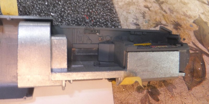
Now getting back into the cockpit. First the ingenious process Tamiya came up with incorporating the weighted cockpit floor/nose gear bay is really something. Slipping the plastic portion into the metal section in a way that will be disguised as part of the interior.
-
1. Plastic portion slips easily into place
2. The exposed metal portions will be painted RLM66
-
1. The exposed metal section will be painted RLM66
PE side panels are placed in the rear compartment. On the LH side rear section.
-
1. LH PE panel in pilots compartment
-
1. This panel in radio compartment LH side
-
1. Panel in place LH rear
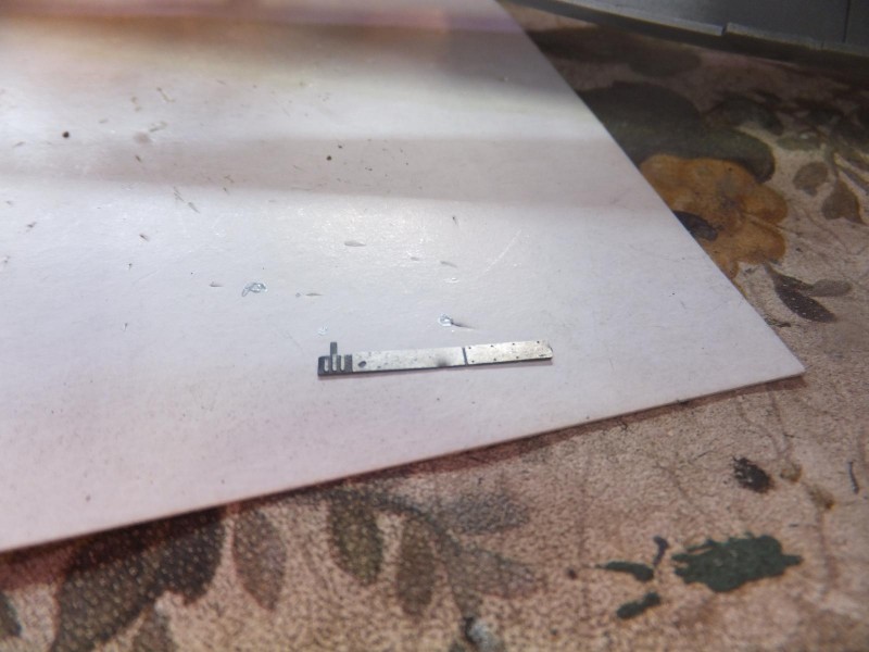
Next it to attach more PE bits to enhance the cockpit. The side rail will be installed on the LH side part of the cockpit between the pilot seat and rear divider. Then the document pouch is assembled and attached in place in the RH rear wall of the radio compartment. Also gauges and solenoids are also placed on the RH side wall in the pilots compartment.
-
1. Rail panel is in radio compartment
-
1. map and document pouch
-
1. Pouch in place in RH rear in location
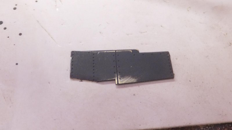
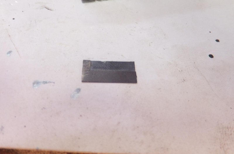
Next the instrument panel is prepared for the PE bits.
-
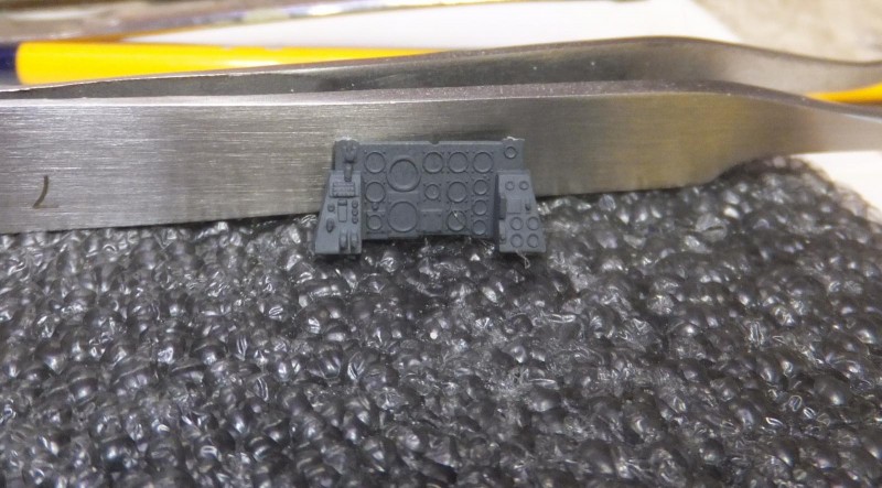
1. details sanded off to accept PE replacements panels
The details are sanded off, then each PE panel is attached with Testors Clear Cement starting with the main center dial/gauge panel. Then the cover is next, carefully aligned to view each dial and set in place.
-
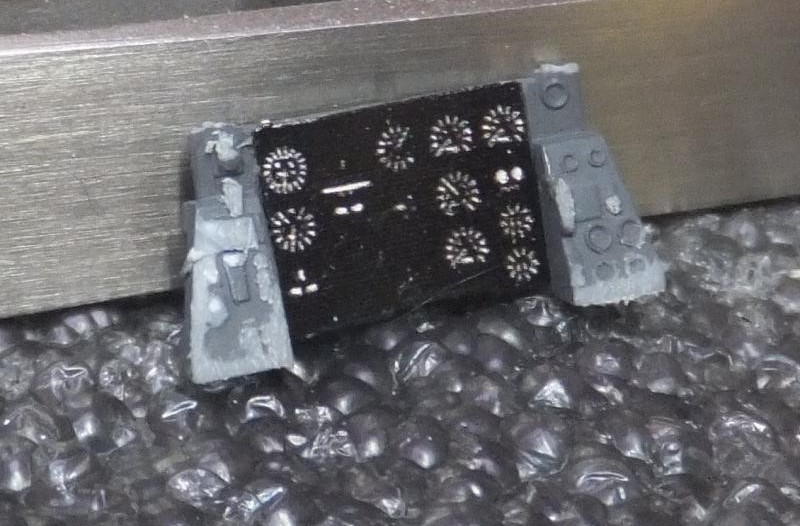
1. main gauge and dial panel attached
-
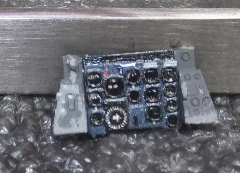
1. Next the IP cover panel is overlayed over the dials
Then each side panel is attached to the IP and set aside to let it set for a couple of hours
-
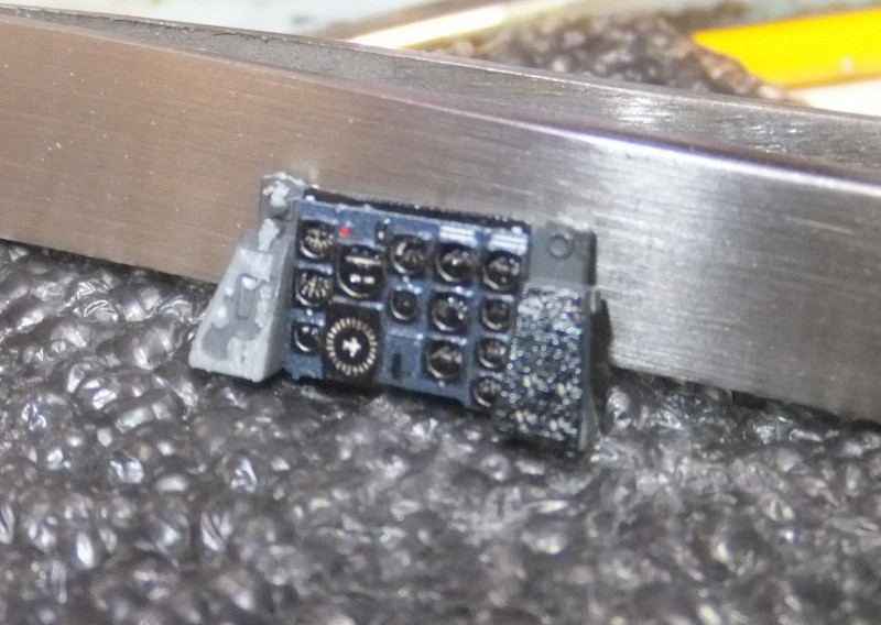
1. RH side console is attached
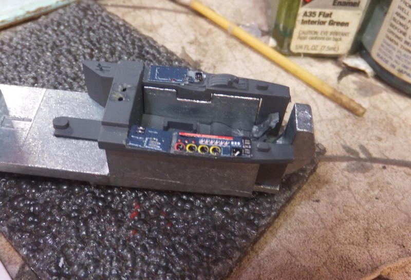
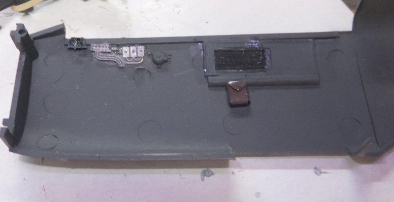
In the meantime, time to work on the radio set and avionics in the rear compartment. Using Nato black to highlight some of the components.
-
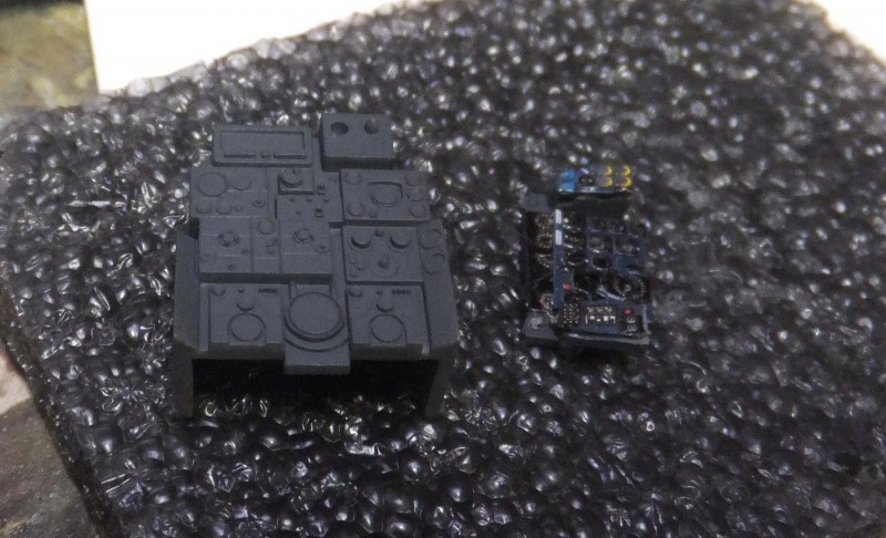
1. IP
2. Radio set and electronics
Put that aside before adding more detail. I install the IP in place in the cockpit.
Navigator/radio operator seat is installed facing rearward. The floor being metal helps in highlighting foot traffic wear by simply rubbing some paint off.
-
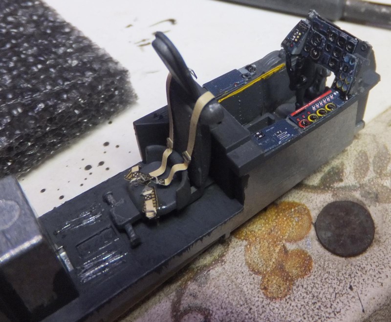
1. the floor being natural metal really helps when slightly scuffing the paint off the floor for wear areas
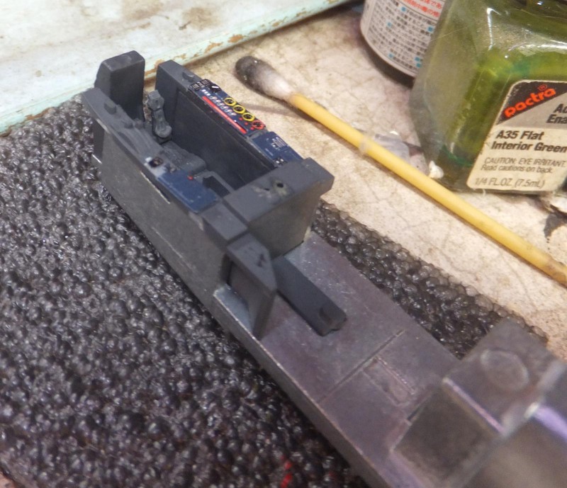
Next after some detailing with silver pencil and picking out some knobs. The radio set slips into place on the rear bulkead.
The pilots seat is then placed in the cockpit.
The PE fuse panel is place into the RH side of the fuselage wall.
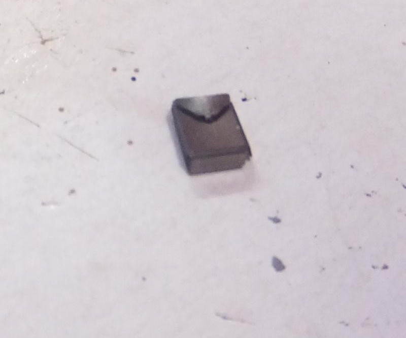
The visor/hood is cleaned up and is installed in place on the radio/radar set.
-
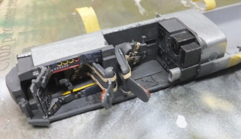
1. The view hood in place
Next up to get this all buttoned up. More to follow.