Lindberg's Crashed Mail Plane
History
Courtesy of Peck Aeroplane Restoration
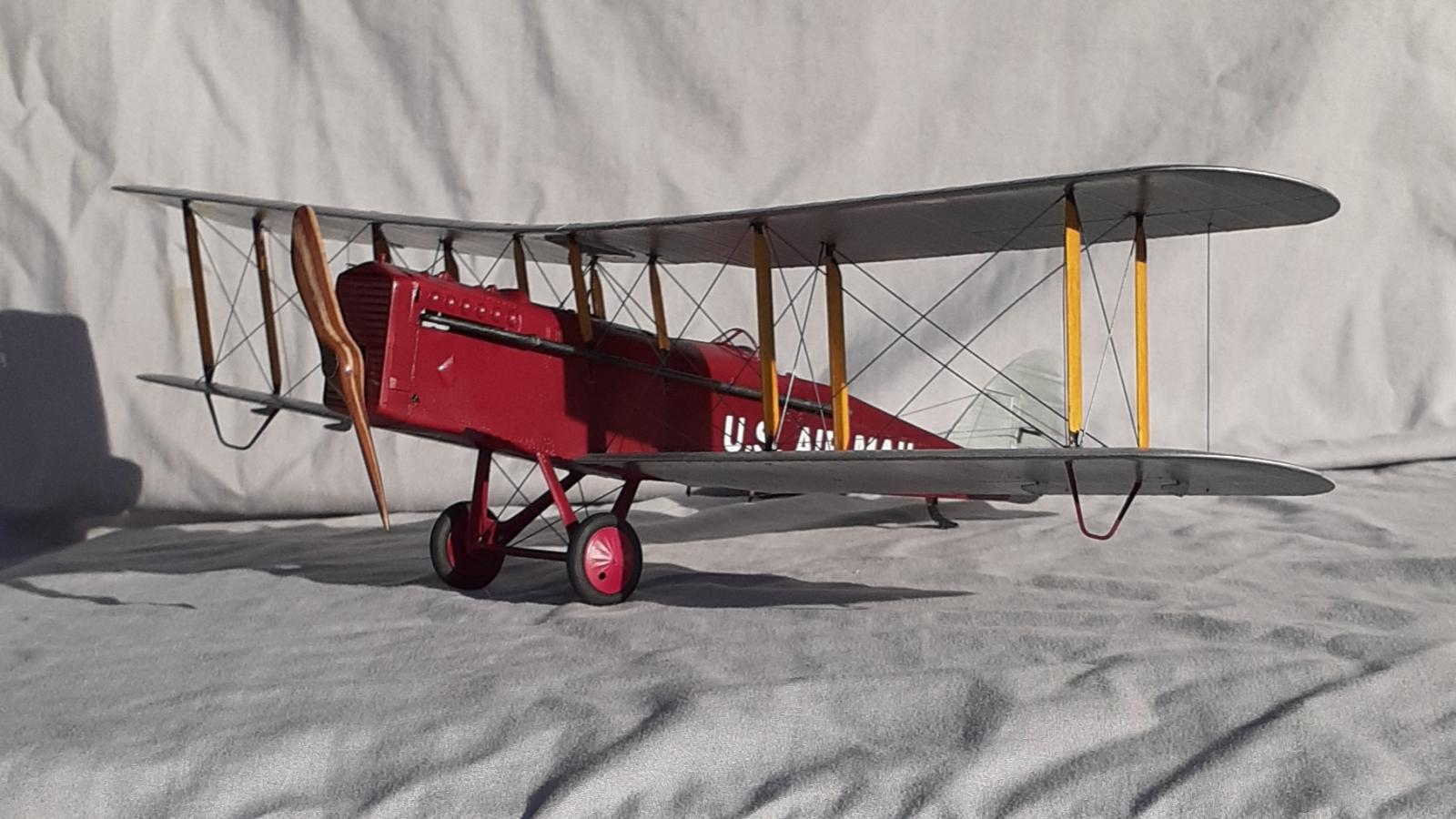
The DH-4 was the only U.S. manufactured aircraft to engage in combat in WW I. With the 400hp Liberty engine (the most powerful engine of its time) and a wing span of 42 1/2 feet and 30 feet long it could perform quite well at a gross weight of 4400 pounds and cruising speed of 125 MPH at sea level. Lightly loaded it was faster than the German fighters of the time, right up to the closing days of the war. It was produced in greater numbers than any other aircraft. When the production was terminated in March 1919, a total of 4,846 had been built. Due to its excellent performance and “always being there”, it dominated the post war service until the late 1920's. In 1920, a steel tube fuselage was created using the other parts of the DH-4B. The steel fuselages were safer and were in service as late as 1932. Boeing Company built 180 DH-4M-1s and later another 150, while Fokker American's Atlantic Aircraft Corp. built 130 DH-4M-2s. The M-2 fuselage is made of larger, heavier tubing
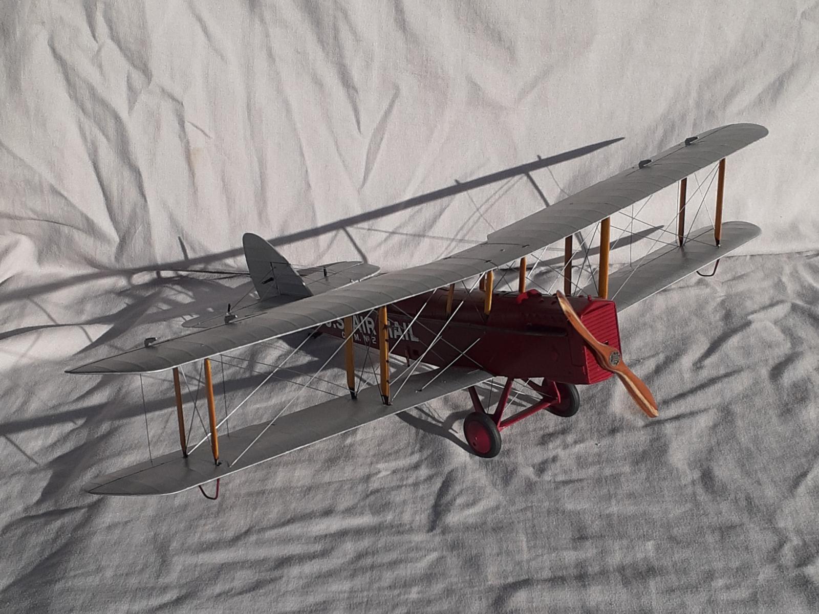
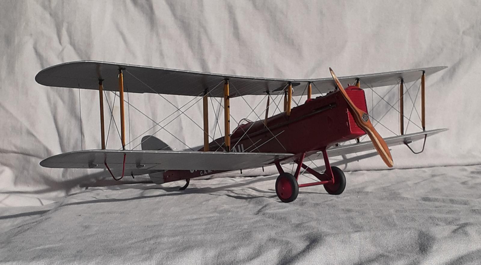
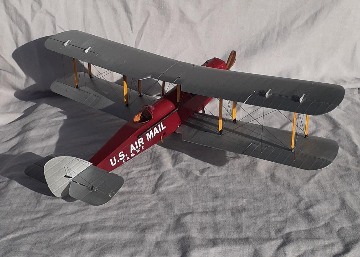
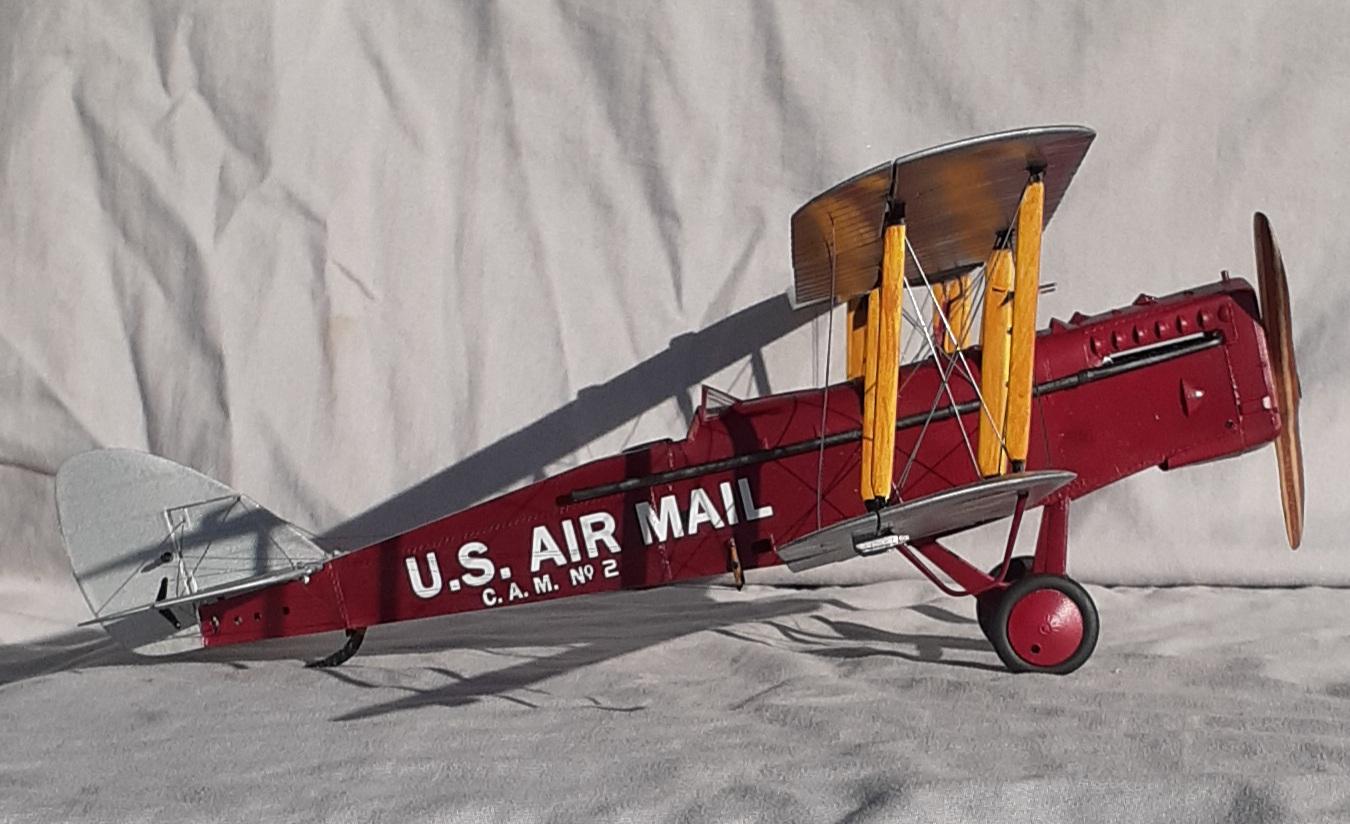
Many DH-4s were used by the Postal Service during the 1920's, and many of the later ones were M models, after they were released from the military. This unit, being built up for the Historic Aircraft Restoration Museum, is an M-2, and will be converted to a Mail Plane as used by Robertson flying Service on the C. A. M. 2 route between Chicago and St. Louis. Charles Lindbergh was a mail pilot for Robertson, and one of his log book entries refers to a metal DH-4. That particular aircraft was actually an M-1, but the sketchy records still available indicate that Robertson did have a few M-2's sometime after Lindbergh left the company.
Courtesy of USPS Airmail history
The Dayton-manufactured de Havilland DH-4 (with modifications and a name change to DH-4B) would become the aircraft that built the airmail service, with over 100 planes in use. The plane was first given by the army to the Post Office as war surplus. The DH-4 had been a successful military aircraft, but as the Post Office discovered after several flights, it needed several alterations before becoming a successful airmail plane. As an airmail plane, the DH-4 had many inherent problems, including a weak frame, poor wing fabric, and landing gear that was too frail for its new mail-carrying weight. The plane was improved with a sturdier, stronger fuselage, a move of the gas tank forward for balance, and a switch of the pilot's seat from front to back.
The changes had many advantages, not the least of which were crash survival rates (pilots were no longer trapped in crashes between an engine and exploding gas tanks in front and hundreds of pounds of flammable paper in the mail bags in the back). The deadly crash rate of the DH-4s resulted in five deaths in 1920, giving it the nickname the “Flaming Coffin.” The greatly altered plane was dubbed the DH-4B. The DH-4B could hold 500 lbs. of mail and fly as far as 350 miles. The DH-4B also had a lengthened exhaust pipe that kept smoke out of pilot's faces. The DH-4B was beloved by the pilots for its reliability and control.
Courtesy of Charleslindberg.com
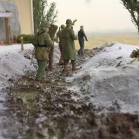
Because the Army was not recruiting pilots upon graduation, Lindbergh was free to find civilian employment. Whilst flying around St Louis Lindbergh had met two war veterans, Bob and Frank Robertson and together they applied for the Chicago to St Louis route, which was known as Contract Air Mail Route No 2. Lindbergh flew a de Haviland DH-4 over the route, with stops at Springfield and Peoria. During this period, he twice had to bail out from the mail aircraft, and although on the first occasion the mail was destroyed, some of the mail is believed to have survived the second crash, as one piece has been found.
The Kit
Packed inside a cardboard box are 11 light-gray sprues, one clear sprue, a photo-etch fret, a large decal sheet for three RAF aircraft, an RAAF Australian aircraft, and a Russian example. Capping the contents is a 22-page instruction booklet printed in glossy color. Two of the smaller sprues hold parts for armament. Rigging material is not supplied.
The Build
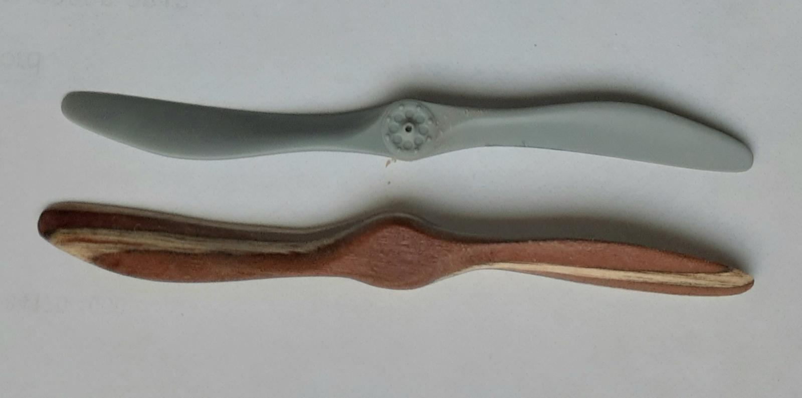
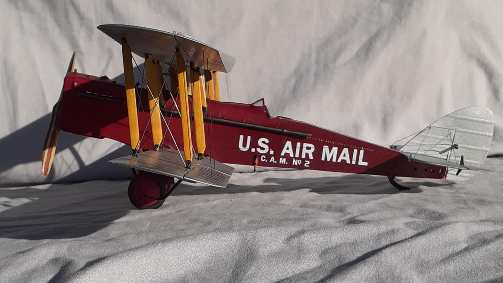
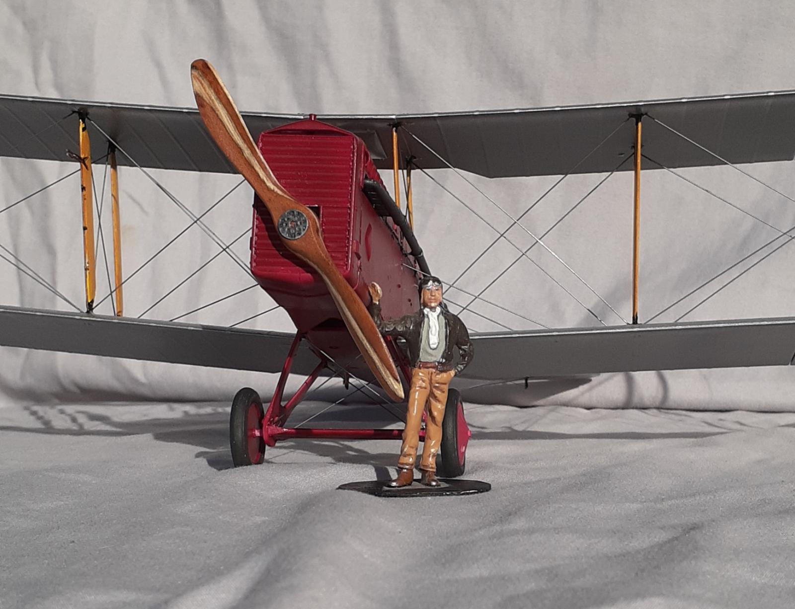
Just to switch things up, the build started by laminating strips of wood to carve a prop. Using a rotary tool and the kit prop as a template, a coarse bit was used to remove most of the material and, as it took shape, finer bits were used. At the end 220 and 320 grit sandpaper completed the forming. A couple coats of acrylic floor polish, sanded in between resulted in a good prop. A photo-etch prop boss finished it. (I wish someone would 3-D print a variety of bosses with nut details.) The whole process took maybe three hours.
Looking at the rigging diagram, the molded in holes for said rigging were identified and enlarged slightly and drilled deeper for turnbuckles. There is tab for mounting the forward firing machine gun on the left of the front cockpit and this was removed and the area smoothed over. On the lower right wing, a open space between the first and second ribs is present. This was blanked off and sanded smooth. The same applied to the camera hatch below the rear cockpit.
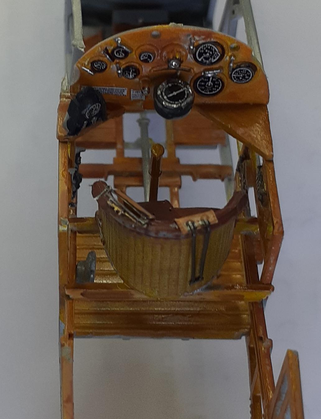
Getting close to gluing parts together, the interior of the fuselage and the relevant wood structures were painted to simulate wood grain. Finally, the cockpit floor was assembled, ignoring the front cockpit parts. A large fuel tank façade piece came next. I debated not bothering with it, but decided that it would add structural strength to fuselage. Each fuselage frame comes in two pieces, so they were mated together and the relevant pilot controls were glued to appropriate locations in the rear cockpit. The ammunitions drums were omitted. After a bit of filing, the floor and frames were glued together.
Before painting and decaling the instrument panel, it was dry fitted to the frame and the fuselage halves enclosed over it to determine the exact shape, location, and gluing process. Once that was settled upon, the panel was processed and attached. The wicker textured seat, leather cushion, and photo-etch seatbelts came next. It was installed using the rear seat mount.
Another mount to install in the fuselage frame was for the engine and it came next. A very detailed engine is included in the kit. Being as the nose would be closed up, only the engine block and prop shaft were assembled and glued in place. The halves were brought together followed by the center bottom piece.
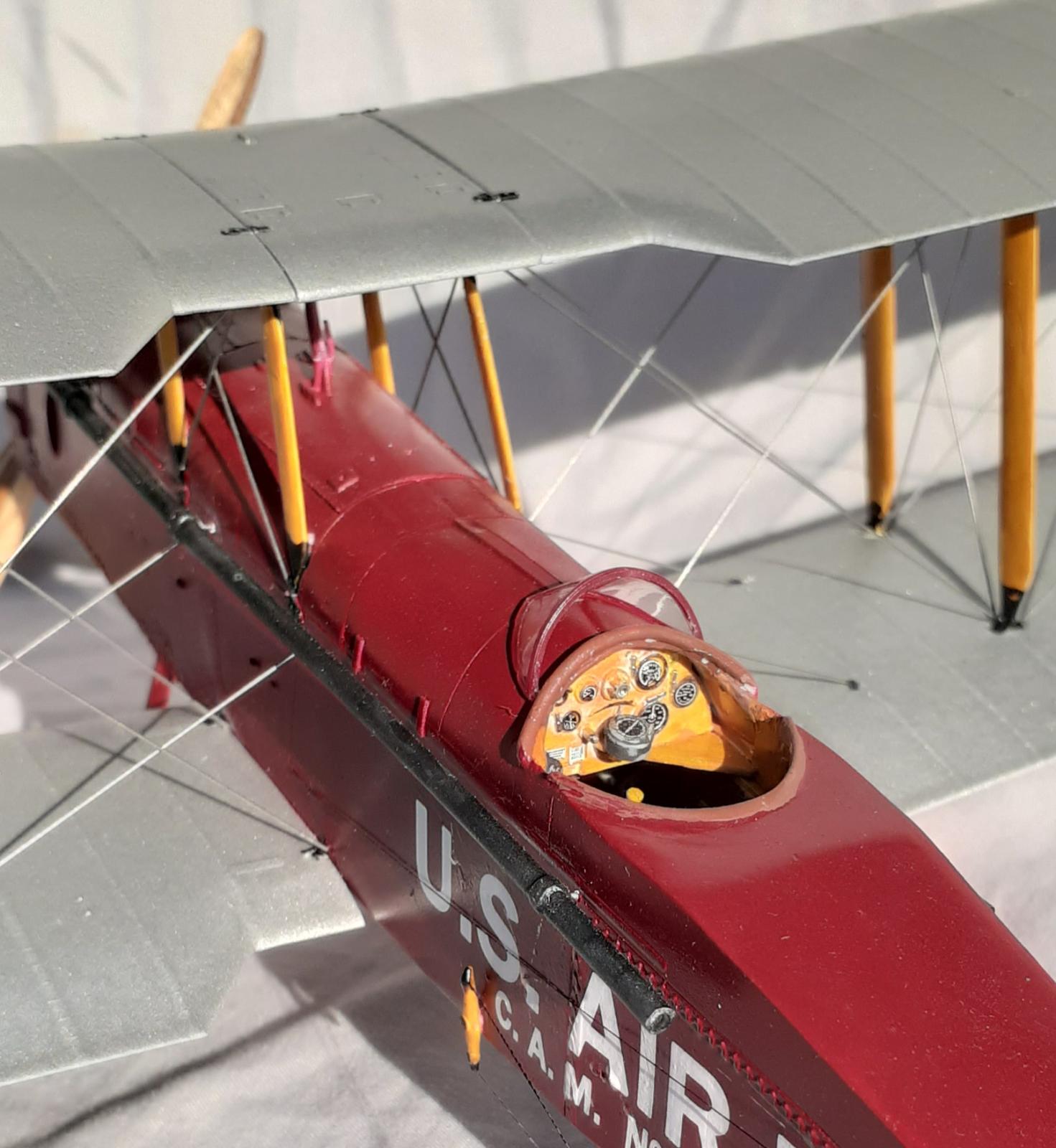
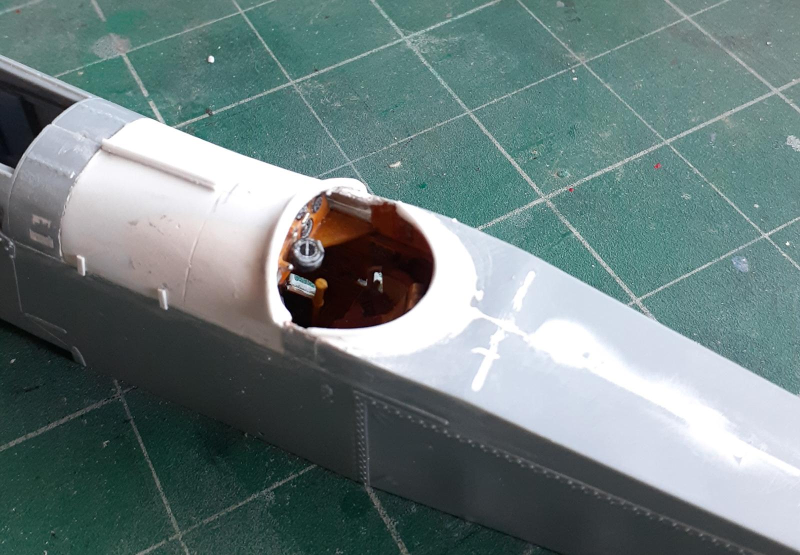
The front cockpit of DH-4s became the cargo compartment in the mail planes and was enclosed a hatch cover hinged on the right side. This was formed by using the instrument panel as a template for a bulkhead and a piece of .020 sheet, cut to shape to cover the compartment and the front of the revised cockpit. Filling and scribing followed, then a small strip of .010 styrene glued to the top, oriented front to back, was glued to represent a reinforcement doubler. Small locking tabs/hinges, also from .010 styrene, were glued on the hatch covers. Scavenged from the parts bin, a windshield piece was modified to fit and set aside for painting and final construction.
The deck behind the cockpit needed cutting down and reshaped. This was done by inserting more .020 styrene to replace the removed material and a couple sessions of filling and sanding. Styrene tube was bent to shape and super glued around the coaming to simulate padding.
Returning to the nose, the radiator subassembly was put together and added to the frame. Before installing the cowl pieces, mounting tabs for the exhaust pipes were glued in place. Extensions for the exhaust pipes were glued on and the location for the external mounting brackets were identified. Those areas were wrapped by .010 strips and holes drilled for pins to use in the final assembly. The rest of the nose pieces were glued in place and some filling was needed. The instructions call for the gun sight, wing tank fuel line, and fuel gages to be added at this point. The sight was omitted and the other pieces saved for later to avoid breaking them off due to handling.
Turning the fuselage over, the landing gear struts and spreader bar was assembled and installed. The locating tabs are engineered to ensure a positive, sturdy fit. Fuselage seams were given the fill-and-sand treatment then the fuel pieces added.
I took more time to add the control horns to the flying surfaces than assembling the upper wing. It is molded in three pieces plus the ailerons and the lower wings are single units plus ailerons. The fin, rudder, stabilizer, and elevator are single pieces, so they just needed clean up at the sprue gates. The ailerons are also separate pieces and these were left off for later assembly. Everything was ready for painting.
Paint and Markings
For the tail surfaces and wings, a 12 oz rattle can Krylon Fusion paint plus primer Metallic Aluminum was used. This is an enamel paint and the graininess of the metallic finish is different than lacquers. The grains are suspended in the thicker enamel binder and, up close, there is a noticeable depth to the finish. The big advantage with the paint was that it held up to extensive handling while rigging.
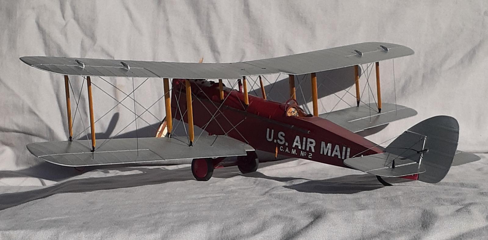
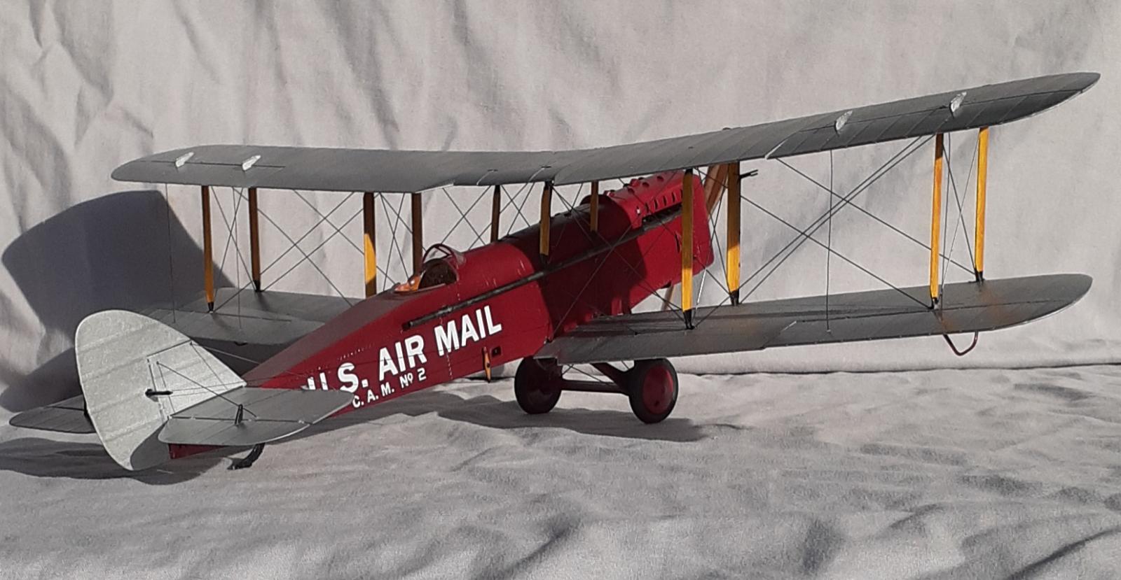
The fuselage was sprayed with Tru-Color's Wisconsin Central Rail Road Maroon, which matched exactly the color on my monitor of the reproduction DH-4 that Peck Aeroplane Restoration built. Tru-Color paints are acetone based and they cure quickly. I found it helpful to use some of their retarder. A side benefit is that, since it smells the same as my sweetheart's nail polish, she cannot complain about the fumes from a painting session.
Thinking that rigged landing gear would hold up better than unrigged during decaling, I experimented with using scale turnbuckles on the rigging. I was unable to keep them in place while tensioning the monofilament thread and loops of the thread were too large for scale. Thinner thread will work better but is too small. (After I finished rigging the model, I found a coated cotton quilting thread that looks like it will work perfectly.) My hat's off to those who can simulate turnbuckles. I reverted to my usual .015 steel music wire.
Bedlam Creations custom printed the decals for me. The white ink is nicely opaque and printed over a full sheet of film. I ordered multiple copies of the lettering and that proved fortunate. While the maroon paint did have a gloss finish, it wasn't glossy enough and I had silvering issues. Another coat of maroon followed and several coats of gloss applied before adding another set of decals. This time it worked well.
Final Construction
Reaching for the exhaust pipes, pins were glued into the mounting brackets and the pipes painted steel, then installed to sides of the fuselage. Leather colored paint was brushed onto the padding around the cockpit and the windshield glued on.
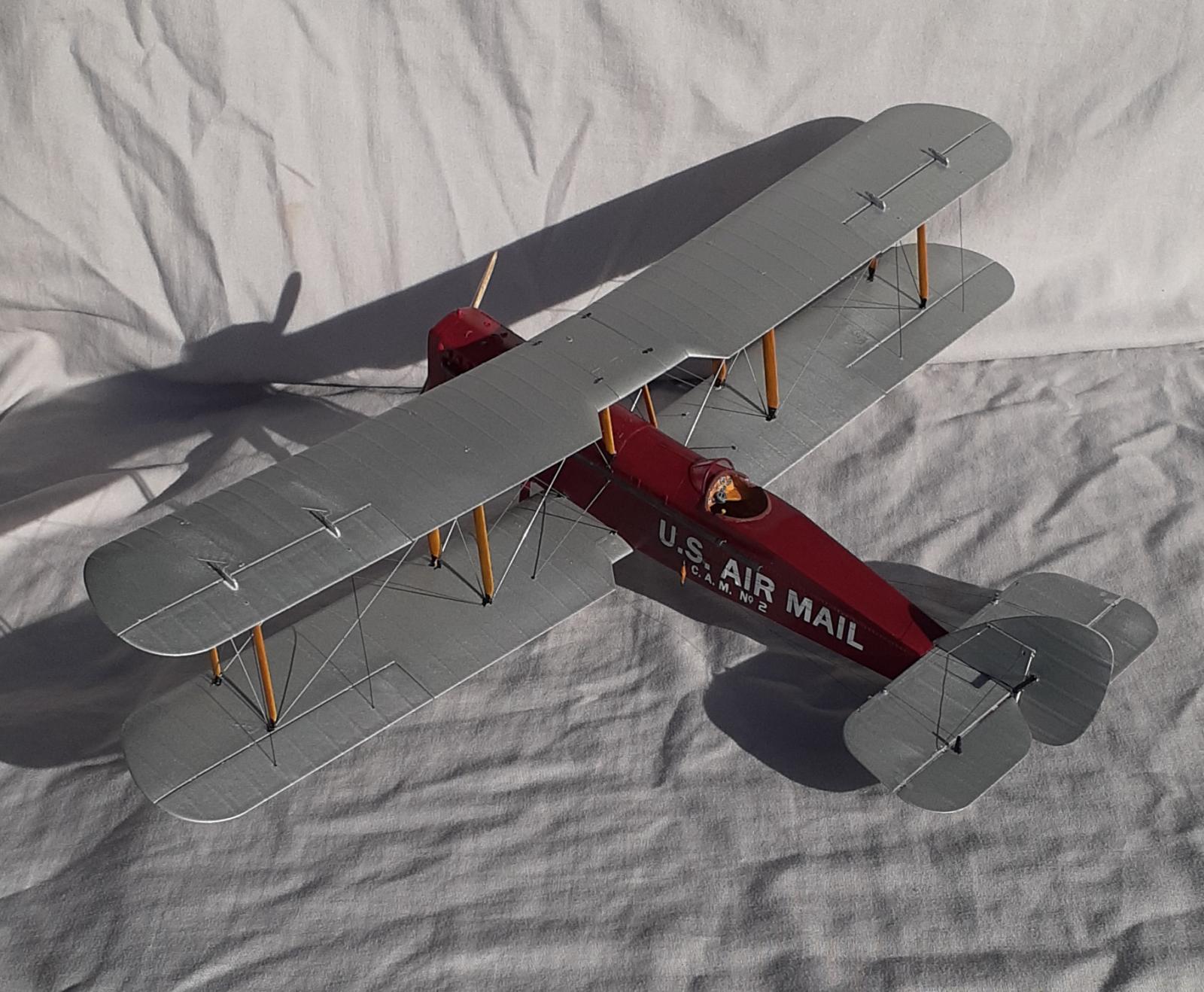
Wingnut Wings' excellent engineering made for easy addition of the lower wings. The correct dihedral is built in to the tabs that slot into the fuselage. The engineering also shines when it comes to installing the struts. They have deep, keyed, sockets to fit into, eliminating most of the alignment worries.
After taking a couple of deep, relaxing breaths, the top wing was glued to the struts. The instructions are clear that one should start with cabane struts and work outward. They also illustrate that as the glue cures, rest the model on the walls of the lower box as a jig to ensure proper alignment. This also facilitates applying drops of glue. After the last drop, I exhaled a breath that I didn't realize I was holding, let the model rest on the leading edges of the wings, called it a night, and went to bed.
Being as a DH-4 (and 9) has four-bay wings, it took several sessions over a week to rig the wings with music wire. It felt like working on two models. An advantage to building biplanes in this scale is that there is lots of room in which to work. A disadvantage is that it's easy bump the model on something while handling it. Not having the ailerons attached also made it easier to rig. Work started at the cabane struts proceed outward. Each step that was completed on one side was mirrored on the other to avoid twisting the wings out of alignment.
When the tail pieces were attached, the end was in sight. Employing the box-as-jig again, it was easy attach the rudder, elevator, and ailerons using clothespins as clamps.
Fearing that music wire as control wire rigging would sag, tensioned monofilament thread was used instead. Slightly larger diameter thread was used for the bracing wire on the fin and stabilizer. Again, work was completed from the inside out—rudder, elevator, then bracing wire. Since the ailerons are the furthest out, they were attached and rigged next.
The last bits were the anti-ground looping skids, tail skid, wheels and finally, the piece that started the build, the prop.
Conclusion
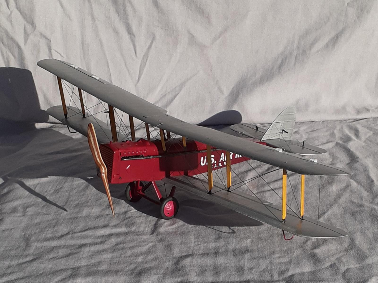
De Haviland reached a dead end after slightly enlarging the DH-4 into the DH-9 and it soon became obsolete. This is evident in details of the kit. Wingnut Wings kits are well-engineered and builders must be precise and patient to assemble one. About 70 hours was spent making this conversion and I estimate that a similar amount of time would be needed if the model was assembled as the intended military version. This is also a large model with a wingspan of 17 and 1/8 inches.
Part of the fun of this build was doing the research plus solving the puzzle of creating the rear cockpit. My reward for doing this project is to have a unique model. I'll probably “do” more Mail planes in the future, especially if a manufacturer comes out with a new mold. I might be able to convert a couple of Hasegawa P-12s or F-4Bs into a Swift Mail plane in Varney markings and a Pitcairn Mail plane.
Welcome, John! Excellent work on this. Your attention to detail speaks for itself. Mail planes are very interesting subjects. One of my favorite models growing up was the Aurora Douglas mail plane. I’d like to see some more issued today. I’d also like to see a new tool 1/48 F4B-4……
Thank you John. I built the Aurora kit and added extended exhaust pipes to that one too. As for a F4B-4, I think see if can get two of the Hasegawa 32nd scale kits, or P-12 and see if I convert them to Swallow and Pitcairn Mail planes.
2 attached images. Click to enlarge.
Nice work on this, John and a really superb result.
Thanks
Another example of the quality work you do, John.
Thanks
That's a beautiful model and prop, your research and attention to detail really made it exceptional!
Thanks. I hope that you learned something from the research.
Excellent job and ditto article, John! Amazing modeling skills! Welcome aboard!
A marvelous effort. Welcome to iModeler (@jsummerford).
Thanks
You entered this modelling forum with an excellent build and ditto article, John @jsummerford
A warm welcome and looking forward to more of your builds.
Thanks. I'm looking forward to posting progress builds in addition to reviews.
That is an excellent model and a great article as well! 👍 Some really impressive modeling skills are on display here, John @jsummerford! Welcome to iModeler! 😃
Thanks. I'm glad that you enjoyed the article too.
Super build and article - enjoyed it a lot.
Thanks
🙂 ... Greetings ... 🙂 :
Splendid and enjoyable work John.
Well done, John (@jsummerford). Your research on this plane, as well as all of your added details, really make this a standout. I have the old Aurora Mailplane, but it will probably never be built because it has one too many wings.
Thanks. The Aurora kit builds easily enough. Like any biplane, it's the rigging that is the challenge.
Very interesting read and a beautiful model, welcome to iModeler.
Thanks. I'm glad you like my writing.
Beauty!
Welcome to iModeler...
Thanks
Beautifully done - don't see that very often (if ever!).