Grumman Goose Airliner
In 1936, a group of wealthy residents of Long Island, including E. Roland Harriman, approached Grumman and commissioned an aircraft that they could use to fly to New York City. In response, produced the Model G-21. It was a high-wing monoplane of almost all-metal construction—the trailing half of the main wing and all the flight control surfaces except for the flaps were fabric-covered. It was powered by two 450 horsepower (340 kW) Pratt & Whitney R-985 Wasp Junior nine-cylinder, air-cooled, radial engines mounted on the leading edges of the wings. The deep fuselage served also as a hull and was equipped with hand-cranked retractable landing gear. First flight of the prototype took place on May 29, 1937.
The fuselage also proved versatile, as it provided generous interior space that allowed fitting for either a transport or luxury airliner role. Having an amphibious configuration also allowed the G-21 to go just about anywhere, and plans were made to market it as an amphibian airliner. Grumman was able to scale down the design into the Widgeon and scale it up into the Albatross
The Goose was Grumman's first monoplane to fly, its first twin-engined aircraft, and its first aircraft to enter commercial airline service. During World War II, the Goose became an effective transport for the US military (including the United States Coast Guard), as well as serving with many other air forces. During hostilities, the Goose took on an increasing number of combat and training roles.
The Kit
Produced by Czech Model, a single bag holds three sprues of gray, hard styrene totaling 49 parts. Resin parts, including multiples of seats, engines, struts, and wheels are molded onto 12 stubs. 10 clear parts are in separate bag.
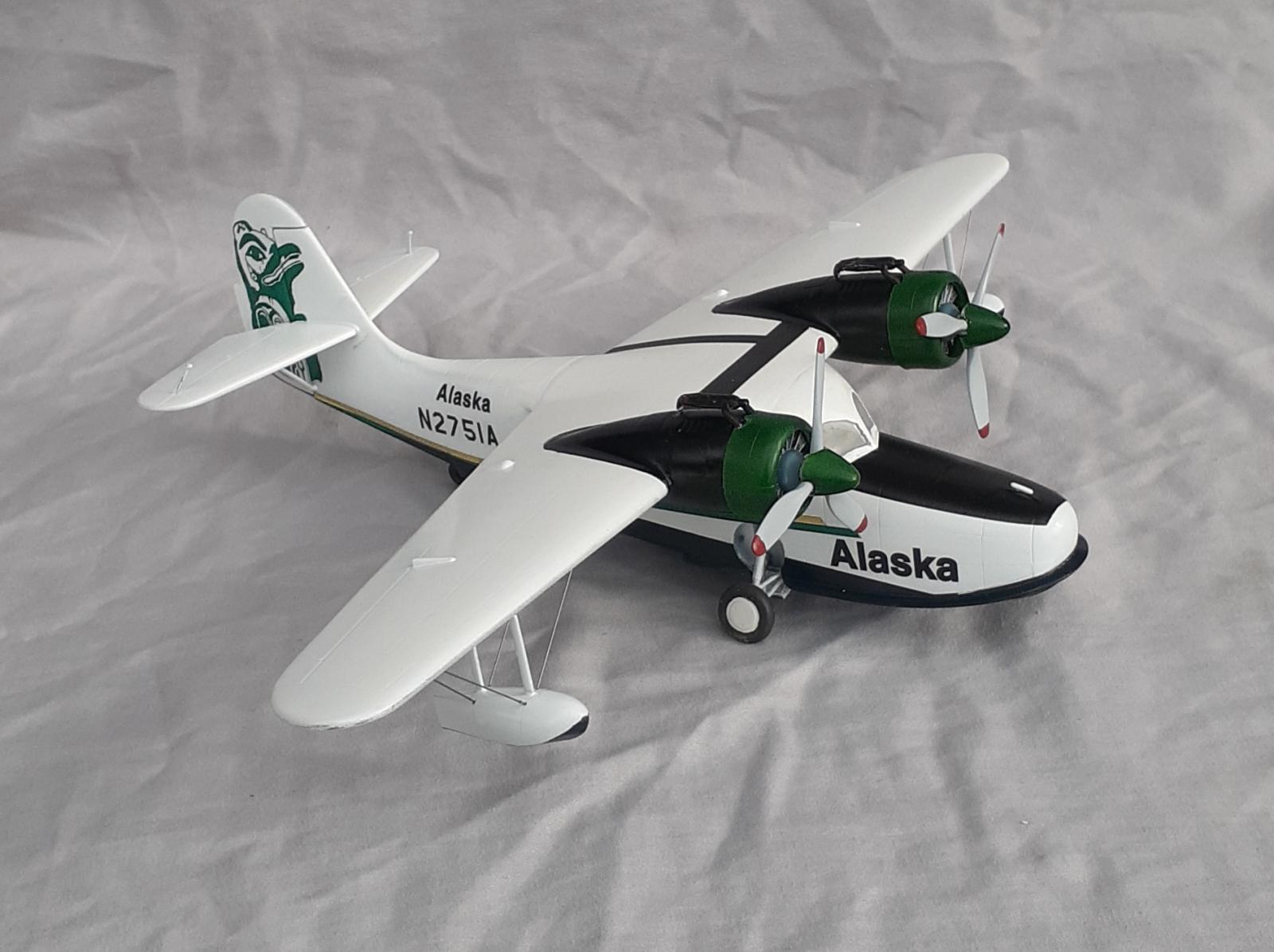
Four colorful options of decals are on two large sheets. Subjects are; a US Coast Guard plane without a reference date; Aviaciaon de Marina de Guerra de Cuba, circa 1945; Swedish Air Force, also undated; and US Army Air Corps, Wheeler Field, 1941
Instructions are on a glossy, 11 by 17 sheet folded into quadrants to fit in the box.
The Build
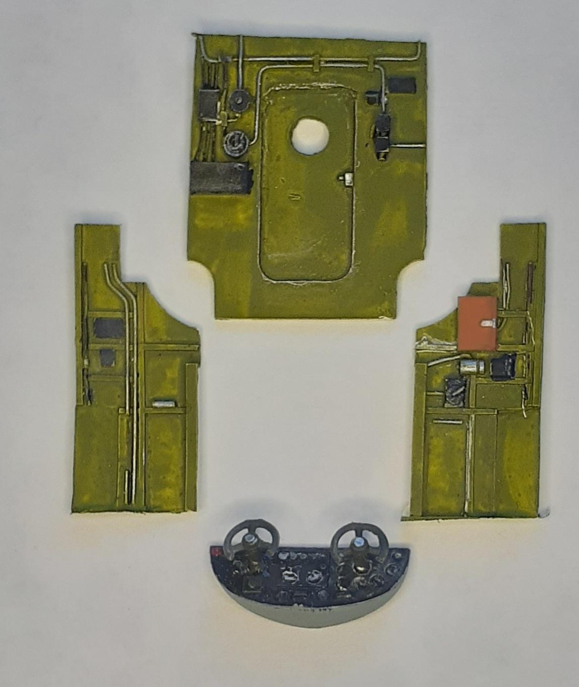
Construction begins with creating subassemblies of the instrument panel plus yokes, rear bulkhead plus tail wheel, and the engines enclosed into the cowls. The panel was painted flat black, and when that cured, swiped with an artist's pencil to highlight the dials and daubs of red paint over switch covers. The assembly was completed with the addition of the yokes and painted rubber.
Before moving on to the interior, the mating surfaces of the fuselage and wings were cleaned up and given numerous test fits.
Painting and highlighting the interior pieces was done before installing the cabin windows and wheel wells from the inside of the fuselage halves. The seats were glued to the floor piece and that assembly attached to the right fuselage half. After trimming the cockpit sidewalls, they were installed next, followed by the instrument panel. Also added were the rear cabin bulkhead and the front bulkhead.
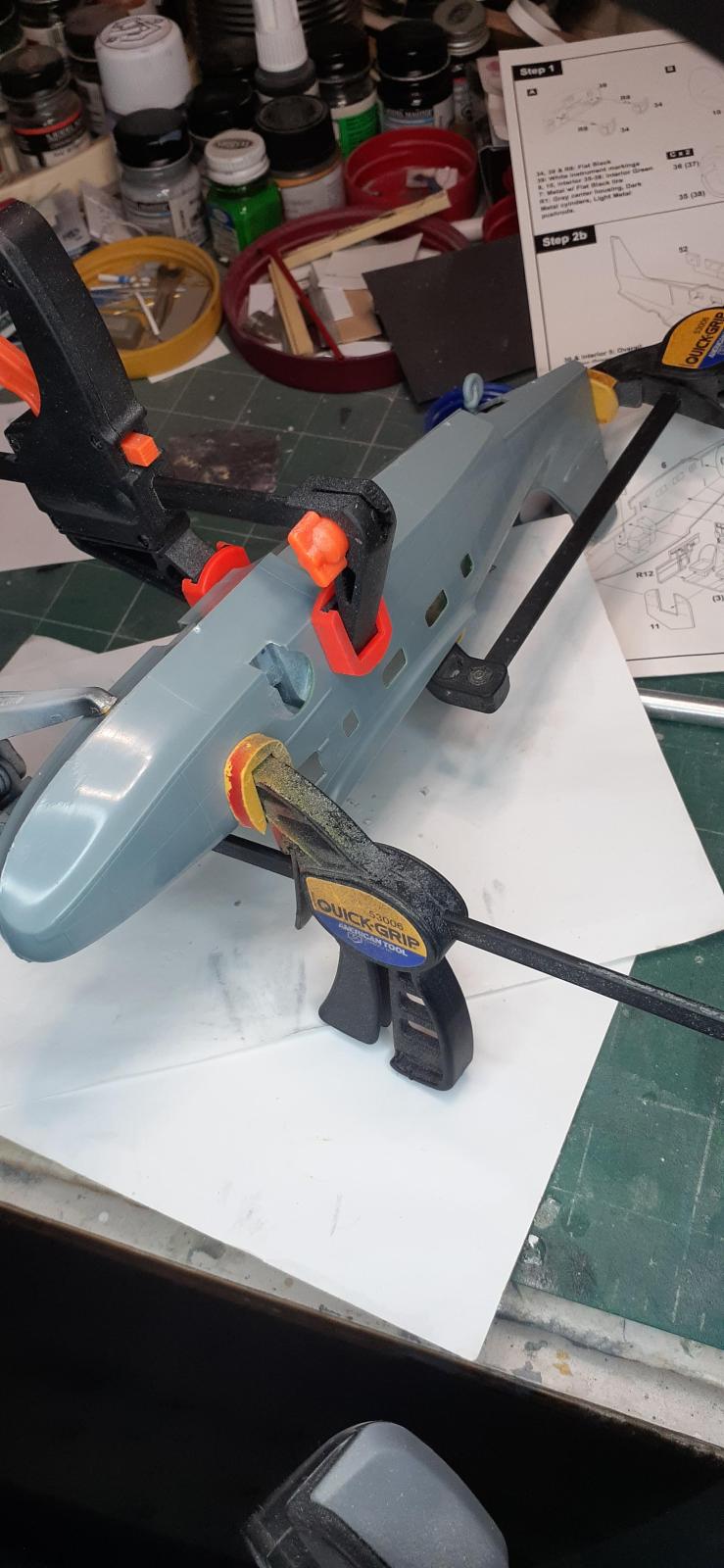
Despite the careful test fitting and sanding, the windshield opening in the fuselage would align, or the panel lines would, but not both. Thinking it would be simpler to install the windshield if the opening was aligned versus re-scribing panel lines, it was chosen as the alignment point. Numerous clamps were employed to keep the halves aligned as closely as possible.
Some filing was needed to get the tail pieces in places, but after dealing with the fuselage, it was easy to do.
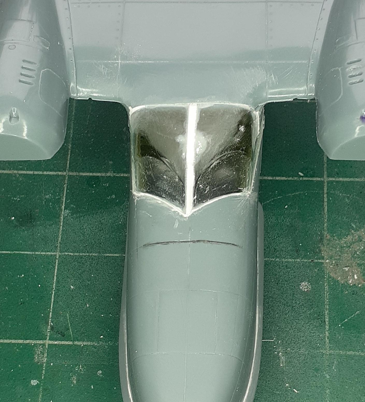
Instead of gluing the lower wing pieces to the single-piece upper wing, then mating the wings to the fuselage, the trailing edge of upper wing, after trimming, was glued to the fuselage letting the leading edge to float. The two-part windshield was glued together. Unfortunately, during numerous test fits, the pieces separated, so each half was tested individually. When they fit, the leading edge of the wing and fuselage were glued together. As feared, the windshield pieces did not fit well in the opening, leaving a gap in the middle. That was filled with shims and blended into the wing.
Masking was done to the clear parts to protect them while the lower wing parts underwent yet more filing and test fitting.
When the wing-to-fuselage joint was acceptable, the chine on the nose as added. When I removed that piece from the sprue, I discovered that the correct way to do that is to saw each gate from the back to the front. I clipped it front to back and broke it. Despite my best efforts, I didn't get the two pieces aligned and the nose looks like it has a sneer. I also had to re-glue it several times during subsequent handling.
Holes were drilled for the rigging of the outrigger floats and they were assembled, again with plenty of filing and sanding.
A pair of metal three-bladed props salvaged from a long-gone B-17 model were shortened and reshaped. Spinners were fabricated from the noses of a pair of drop tanks.
Everything was given a coat of primer, which revealed that more filling, sanding, and re-scribing was required in numerous places. Eventually, the model was ready for paint.
Paint and Markings
Starting with the hull portion, the fuselage sides were masked and the bottom painted dark gray. When masking the gray, the tape lifted the paint from the primer. (Sigh! Really? Oh well, return to that later.)
A rattle can of new Testors gloss white was sprayed in stages on the model in stages. During coating the upper wing surface, I remembered why I don't usually use spray cans when a drip splattered just in front of the left aileron. That required sanding and repainting.
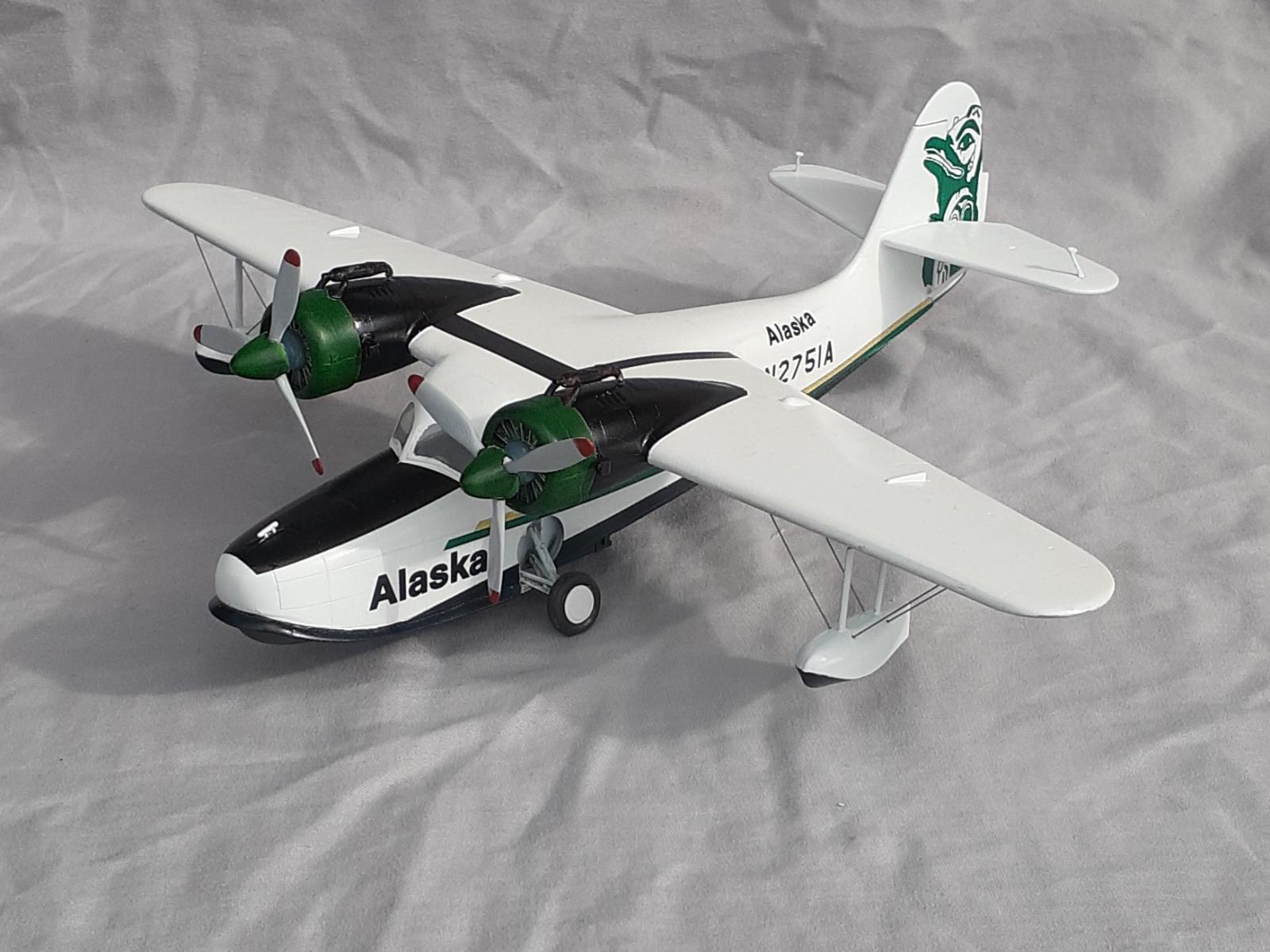
With the white coat done, the nacelles were masked around and painted black, also from a rattle can. That proved to be a disaster with numerous issues, so they were repainted white and masked again, then airbrushed with gloss black enamel. While that cured, the cowls and prop spinners were painted green while the props were done in gray with red tips.
Returning to the underside, that was masked and painted with Gun Mettle enamel.
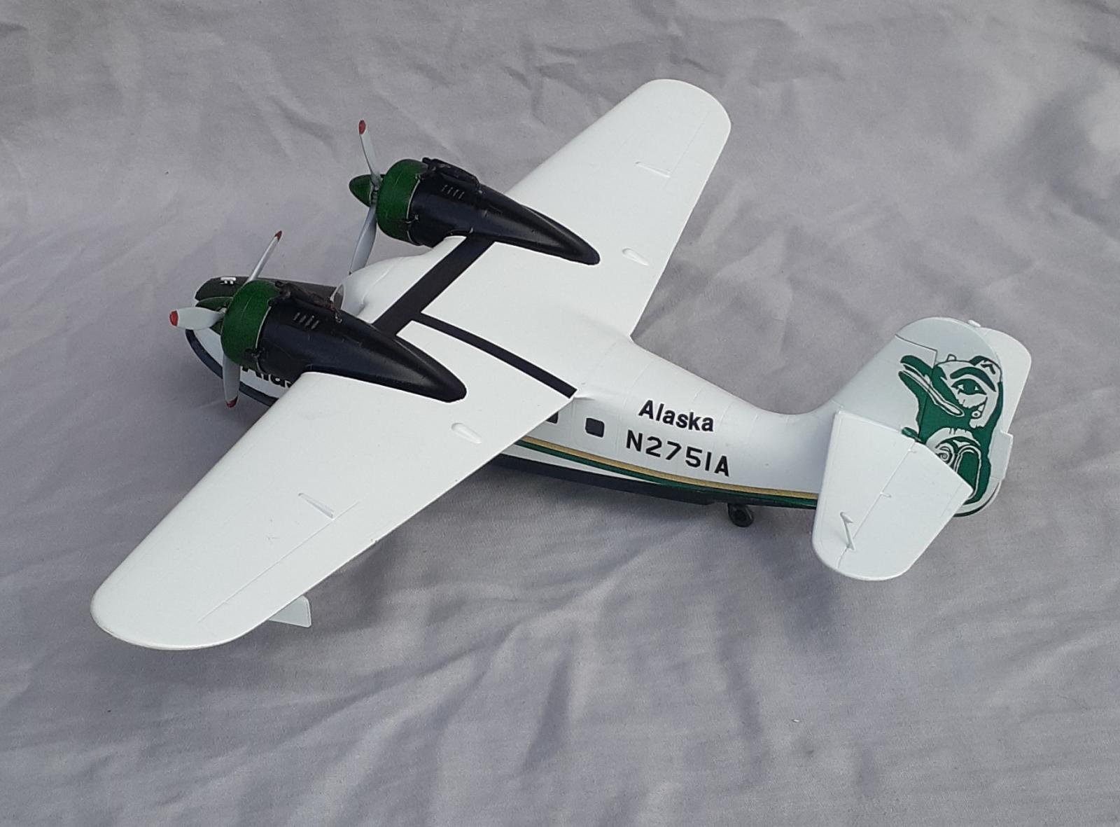
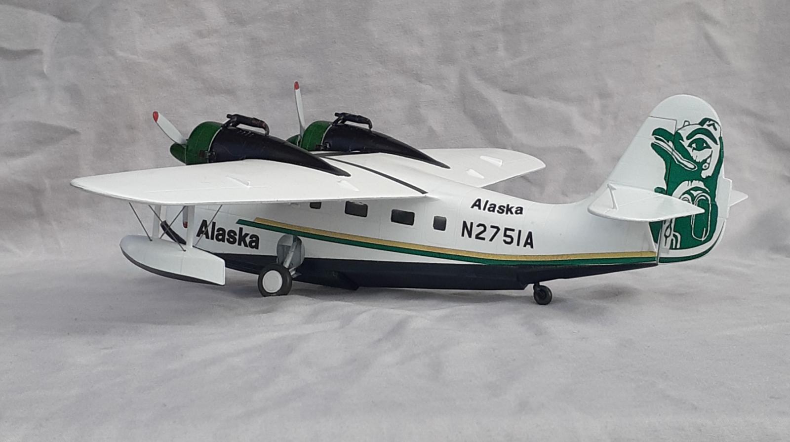
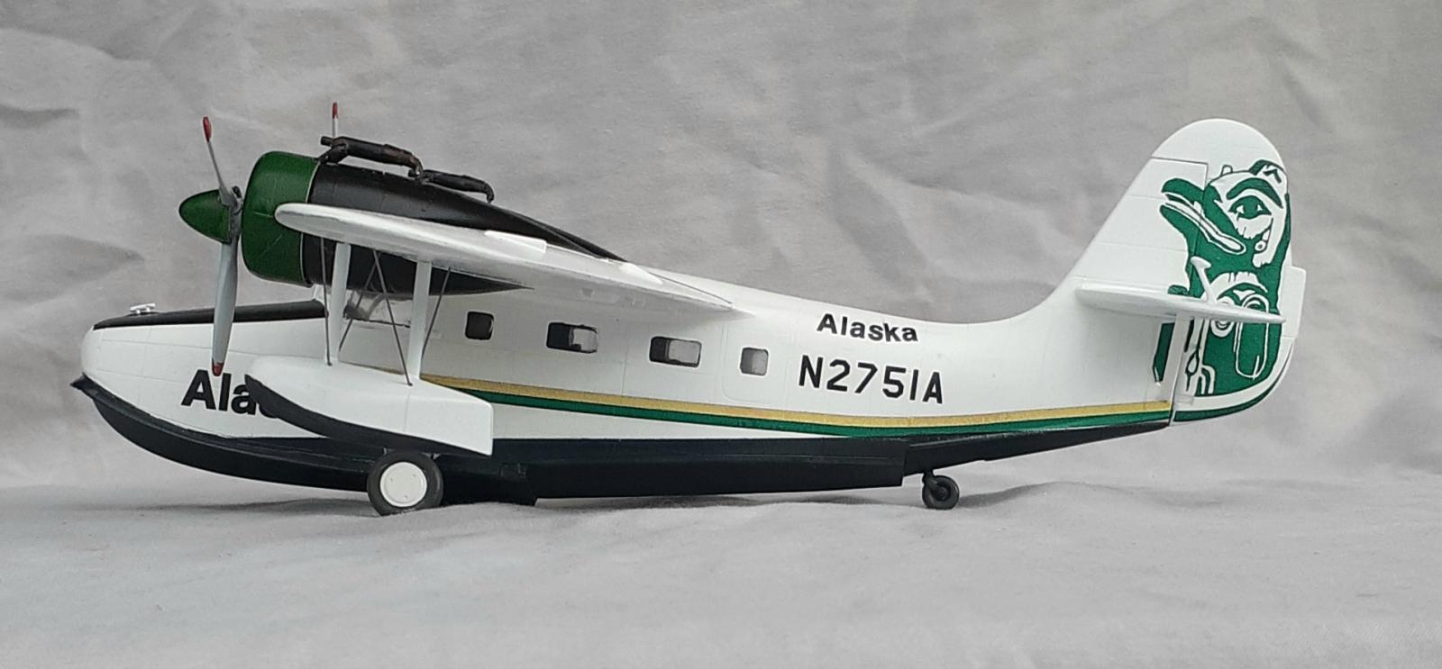
Draw Decal prints each order on demand over a continuous sheet of clear film. A nice four-color, double-sided instruction sheet is included. For this set, the markings are for a later variant of the Goose, notably with the outrigger floats folding up to form the wing tips. One item to be aware of is that a notch must be cut in the totem graphics for them to fit around the stabilizer. The totems were sliced in two horizontally and the notch cut on the lower portion. The instructions also advise the modeler to source the previously mentioned three-bladed prop.
Applying the decals was straight forward and they behaved nicely.
Final Assembly
Even though the landing gear looks complex, installation is easy. Use of liquid cement makes it possible to maneuver the struts and upper braces together before the joins cure. The lower braces are almost an afterthought. Adding the doors and wheels completed that area.
The floats are wobbly until they can be rigged. Steel .015 music wire solidified them very well.
Flipping the model over, the engines were glued to the nacelles and then glued to the wings. The exhaust systems followed. The mass balancers were added to the elevators then the props, finishing the build.
What a superb build John! Beautiful paint job.
Thanks. I hate having to re-work paint, but that is what needed to be done.
All that work produced a great model, John.
Thanks. I keep thinking that I want to do an easy, relaxing build, but seem to get mired in challenging builds. Well, maybe some day.
Super-cool, John.
I'm glad you like it.
Very nicely done!
A wonderful result out of the challenging Czech Model kit, John!
Congratulations!
Thanks. I thought, that such few parts and simple decals, it would be an easy project. Still, it was fun.
What a great result! Definitely worth all the effort to "get it right."
I still kick myself for not picking up the sheet of decals for the Catalina Island Air Service Goose at the 2007 IPMS Nats. I actually flew over to Catalina in the Goose waaaaaayyyyy back in 1967, when we had to dodge the roaming tyrannosaurs to get to the airport. 🙂
Thanks Tom. Take a look at Chas Bunch's (@chasbunch) comment. I probably would have snatched a set of those decals.
Excellent result on this far from easy kit, John @jsummerford
The build and painting looks awesome.
Thanks. Have you built this kit?
Well done, it looks great. I did that Czech Model kit a few years back, your build description brought back some memories. I didn't realize that the Goose preceded the Widgeon, thanks for the history of its beginning. I learn something here every day!
1 attached image. Click to enlarge.
Thanks for the photo. I worked with curator who was fond of saying "It's a sad day if you don't learn something new." My familiarity with the Goose is from a retrospective book written by Bill Gunston, "GRUMMAN sixty years of excellence" that I bought in the late 1980s Two pages are devoted to the Goose. Now, with the internet and Wikipedia, it's easy to do research and copy/paste text and photos. I enjoy doing the research before starting a project for that reason.
Nice Goose!
Thanks. I'm amused to read the compliment. I've never had anyone say or write to me.
Very nice project - love those markings, a real "looker!"
Thanks. I'm glad That I got there at the end.