Saturn V Mobile Launcher – hard stand support pedestals
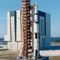
Most Saturn V mobile launcher/LUT models use the LUT to show off the crawler/transporter that transported the complete stack from the VAB to Pad 39, as shown above. As handsome as this, I decided to show my LUT on the pad instead for two reasons.
First, I wanted to show the stack "launch-ready" and while being carried out to the pad the CSM of the Saturn V is wrapped in white plastic to protect it from the elements, and the launcher deck is covered with equipment that will be removed before launch. I've always assumed the big white box near the rocket is a generator for the launcher's electrical systems while it is travelling, but the point is that it's messy and not flight ready. It's like modeling a B-17 on the back of a flat bed truck being transported to an airfield. It isn't until shortly before launch that the spacecraft is unwrapped and the extra equipment removed, and that's the time period I wanted to show.
Second, the crawler itself is an entire additional model to design and build, and the LUT, with it's detailed piping and swing arms is project enough, So I decided to show the LUT on the pad itself. I may build the crawler later, but for now, the pad is the base I wanted to use. I can add the pad interfaces if I feel like it, or leave just the support pedestals.
The launch pads at Pad 39 A and B were "hard stands", meaning that they didn't contain towers for connecting to the rocket. The crawler brought the stack on the mobile launcher (as shown left for Skylab 2), and lowered the launcher onto six support stands, which contained either one or two support legs. The rocket was then plugged into the pad "interfaces" which are short metal structures containing various piping and cabling, as well as (at far left) the slide to the "rubber room" within the pad that was an emergency shelter in case of catastrophic failure. If you count ten pedestals, you have sharp eyes - the mobile launcher used six, and the Mobile Service Structure (MSS) used the other four. The rocket was then launched, and the photo at right shows the three pedestals on the south side with the first MSS pedestal directly in front of it.
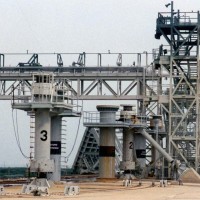
The picture with all-gray hardware from the shuttle era shows two of the same three pedestals (helpfully numbered). The back two still have their side braces in place. They're actually hard to see due to all the background clutter. That's because during the shuttle era the pads had large built in support structures added which eliminated the need for an umbilical structure on the launcher. The structures at the pads were built by the simple expedient of cutting the towers off the Apollo-era launchers and attaching the upper portions to the pads - then attaching the various new structures needed by the shuttles to the old towers.
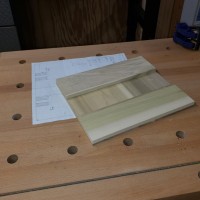
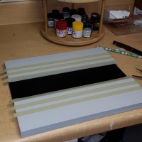
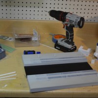
I built the base representing the top of the hard stand out of poplarand primed and painted it before adding crawler track marks. The paint scheme for the concrete pad is a work in progress, as the pad changed appearance as it aged, and I haven't decided whether to leave the flame trench in the middle plain black, or make it simply a darker gray.
It then took some additional research to figure out where precisely to place the six pedestals, since I decided late in the process to move them forward to allow room for the emergency slide which extended out the back of the LUT into the pad to allow access to the rubber room and blast room. (That's why the track marks have been partially overpainted). The base was intended to be just large enough to include all the pad interfaces if I decide to build them - fortunately I made it large enough to accommodate the slide.If I ever get really ambitious and build the MSS, the very large gray structure shown at right which enclosed the CSM and upper third stage to allow additional access at the pad, its four pedestals will fit on a separate base that would match up with the mobile launcher model's base. But I'd likely model it as shown here - at the foot of the pad still atop the crawler. If anyone's ever modeled the MSS it's a safe bet they didn't show it on the crawler.
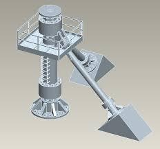
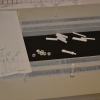
I drilled out holes for the 1/16" plastic rods which serve as anchors for the pedestals, then cut three different diameters of plastic tube to make the basic shape, shown at right.The drawing shows the dimensions of the pedestals, with the dimensions of the component parts.
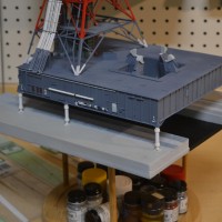
Once the pedestals were in place, and still somewhat flexible on their thin rod bases, I lowered the LUT onto them, where 1/16" plastic studs on the base fit into the pedestals' top pieces. Once the launcher was in place I added small triangular bracing to firm the structure up, as shown below. Next step will be the addition of the large side braces (with foundations) and the square railed platforms to the pedestals, and then it's back to figuring out the right color for the concrete hard stand, circa mid-1969.
Oh, and finishing the LUT, of course.




Michael, this is really some nice work, and what a nice display of work you have there. I still remember these wonderful space race days and moon missions. Its amazing the engineering and science that went into to pulling this off. Well done !
Beautifully done, Michael! There's a whole lot of work no-one will know much about just planning & designing this great build. I'm VERY impressed.
Bravo!