Classic Airframes 1/48 Meteor F. 4
From 2003 with updated photos:
The Airplane:
The Meteor F.4 was the result of three separate lines of research that began shortly after 616 Squadron had taken delivery of their F.1s in 1944.
The Aerodynamic Section at R.A.E. Farnborough was studying ways to improve the high speed characteristics of the Meteor; wind tunnel tests indicated a breakdown of airflow around the engine nacelles at Mach .75, which resulted in a great increase in drag and severe buffeting, with the center section completely stalled. Further experiments demonstrated that these conditions could be delayed by increasing the chord - the length - of the nacelles in front of and behind the wings. Full scale trials on EE211 in November 1944 demonstrated a very useful increase in performance with the longer-chord nacelles.
Secondly, development of the Derwent 5 - a smaller version of the excellent Nene jet engine - resulted in a doubling of available thrust as compared with the Welland.
Thirdly, with the increase in power and aerodynamic cleanup, Gloster decided to go for a world's speed record. This was accomplished with a general clean-up and strengthening of the airframe; all of which was so successful that the result was ordered into production in November 1945 as the Meteor F.4.
The first Gloster G.41F Meteor 4 was a modified F.3, EE360, which made its maiden flight on July 17, 1945. It showed a 111 m.p.h. increase in speed over the standard F.3. Airframe stress caused by this increase in speed was dealt with by clipping each wingtip by two feet, ten inches, which improved the rate of roll considerably, but raised take-off and landing speeds while reducing the rate of climb.
The F.4 did not completely replace the F.3 in front-line service until 1948, though the first production examples had reached squadron service in mid-1946. 539 F.4's were produced by Gloster, and 44 by Armstrong-Whitworth, who had entered Meteor production in 1946.
The Meteor F.4 was the first of the type to be exported, and they served in the air forces of Argentina, Denmark, Egypt, Belgium and the Netherlands. They flew with the R.Aux.A.F. until the mid-1950s, serving alongside the later Meteor F.8 in these units.
The Kit:
This kit represents the first injection-molded model of the Meteor F.4 to be produced since Frog released one in the late 1960s in 1/72 scale, which can still be found but is decidedly primitive. In 1/48 scale, this is the second kit of the F.4 to be available, with Aeroclub having produced a mixed-media kit in the mid-1990s. In 2013, H-K Models released a 1/32 Meteor F.4 as a mainstream injection-molded kit, which is probably the best kit of this aircraft available.
The kit shares the wing and resin detail parts with the earlier F.8 kit, with a different fuselage to cater to the F.4. As with the F.8, the injection plastic is well made, and is very shiny - this should help modelers in getting the smooth final surface to the model that is crucial to getting a good silver finish, of particular importance since the Meteor F.4 was painted in High Speed Silver for all of its operational life with the RAF. The injection-molded canopy can be posed open. Decals are provided for a camouflaged F.4 of the Danish Air Force and a silver F.4 of 263 Squadron, RAF, in 1950 shortly after the reintroduction of colorful squadron markings.
Construction:
Due to the short forward fuselage of the F.4, the kit presents a more difficult problem of getting enough weight ahead of the wheels to make it a nose-sitter, given the shorter moment arm.
With all that in mind, the first thing I did was to glue the fuselage halves together and attach the horizontal stabilizers. I then painted the parts of the cockpit flat black and set them aside. I also glued the engine nacelle intakes together and applied putty to the interior to get rid of the huge seams.
The best way to insure a good fit for the engine nacelles is to be sure that the resin engine face was small enough to fit inside the nacelle with enough room left over for some external pressing and squeezing to get the body of the nacelle to fit to the intake. To do this, you need to have the parts of the wing trimmed to fit to the fuselage before proceeding. There is a small amount of flash on the trailing edge of the lower center section that must be trimmed off, and the rear joint line on the fuselage needs to be trimmed back a bit to insure an easy fit. This is just a process of test-fitting, trimming, and test-fitting again until you have it. The same needs to be done for the upper wing center sections to get a good joint from wing to fuselage.
With all that done, I then painted the resin engine plug and the exhaust, and glued them into position in the lower wing center section, along with the main gear wells (which need to be sanded down a bit on their rear side, to insure good fit between the wing halves). I finished the process by sanding out the interior of the nacelles and painting that area with silver paint. I then attached the lower wing center section to the glued-together fuselage (without gluing it), so that I could fit the upper center sections to that and glue them in the proper position.
There was a lot of test-fitting and trimming to get the nacelle intakes to fit closely to the nacelle, and in the end I still had enough of a "ridge" that it was noticeable, requiring putty and sanding down and several applications of Mr. Surfacer 500 and 1000 - with the resultant rescribing - to get the engine nacelle looking right.
I then turned to the cockpit assembly, which went together easily. Slipping it into the fuselage and test-fitting revealed that the forward bulkhead needed sanding down in order to get it in far enough. I kept test-fitting and sanding until it slid into the fuselage and pushed all the way; when I achieved this, I superglued the cockpit subassembly in position.
Now was the problem of weight. Just piling in weight behind the cockpit on the F.8 hadn't been sufficient, and that was with a moment arm nearly half an inch longer than what the F.4 would have. I took out some lead "cannon ball" fish weights and started squeezing them flat. I could then get 3 of them under the cockpit floor. I kept squeezing the weights flat and attaching them to the rear of the cockpit, which allowed me to stack weight further forward than would have been the case if I had just put them in without squeezing them. With the tail assembly glued on, and the wing easily able to fit to the fuselage, I could keep testing by balancing the model at the point where the main gear is attached to the wing. As it turned out, I used all 20 of the fish weights, and completely filled the area behind the cockpit to the opening for the wing. With that, this Meteor was definitely going to be a nose-sitter!
With the weight problem solved, I glued the wing outer wing panels to the center section - remembering to stuff a piece of sprue into the outer panels to make the outer wing thick enough in section to fit correctly to the center section - and then attached the complete wing sub-assembly to the fuselage. I then set about applying Mr. Surfacer to all the joints and seams. I spent a day sanding down the joints, checking for smoothness, re-applying Mr. Surfacer, re-checking for smoothness, etc. Once that was accomplished, I rescribed the now-missing panel lines, and then polished the entire model with Tamiya rubbing compound.
Painting:
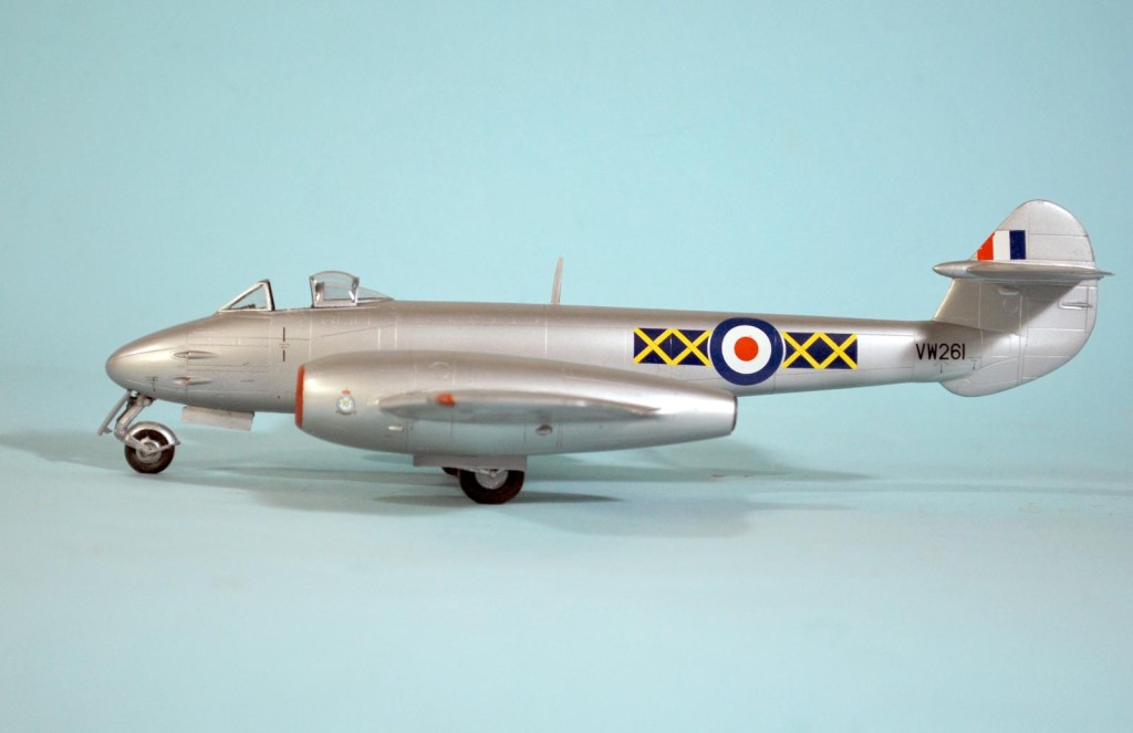
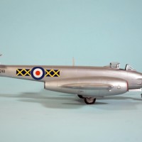
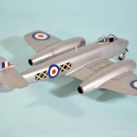
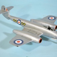
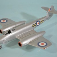
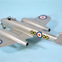
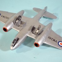
The Meteor F.4 spent its entire RAF career in a coat of overall aluminum lacquer, known as High Speed Finish. This paint did weather a bit and change hues, but only subtly; but not doing this would condemn the finished model to a very monochromatic look. I gave the model an overall coat of SnJ Aluminum paint, then applied Model Master Aluminum (Non-Buffing) Metalizer paint inside panels, with Floquil Old Silver used on the upper surfaces of the wings, stabilizer and fuselage, to simulate the effect of sun. This is all very subtle and the camera may not catch it sufficiently for you to see it on a computer monitor, but it exists in real life. A coat of Metalizer Sealer completed the look of aluminum lacquer, and the model was ready for decals. I hand-painted the red trim around the intakes with Gunze-Sangyo "Shine Red," a bright scarlet red.
Decals:
I used the Xtra Decal sheet 48-046 for Meteor F.4s and T.7s,to do this Meteor as one flown by 609 Squadron, R.Aux.A.F. circa 1952-53, when colorful squadron markings returned to Fighter Command. National insignia and the service stencilling came from the kit sheet. Both sheets are printed by MicroScale and went down with no problem under a coat of Microl-Sol. I have to say I do not think the red color is right - not bright enough - on the kit sheet for the two Squadron markings that are included.
Final Assembly:
I unmasked the canopy and attached the sliding portion in the open position. I then attached the landing gear and gear doors, and the model was finished. These airplanes of Fighter Command and the Royal Auxiliary Air Force were kept very clean in this period, so I did not weather the model further.
Conclusions
You know going in that when you are building any Classic Airframes kit "some modeling skill" is going to be required. I had an easy time of it with this model because I had built three of the F.8 kits and was well up the "steep slope" of the learning curve. However, if you build yours in the order I have described here and follow my suggestions for dry-fitting and application of weights, any modeler with at least a couple short-run kits will have no problem coming up with a final result that looks at least as good as this.
UPDATE: This model has been in storage for 10 years, but when I pulled it out, it was still in good condition, a tribute to the decals and my painting skills.

Great to see the model still in great condition, Tom!
Looking excellent as it did in December 2003.
Great review, as well, a joy to read.
Great looking NMF! Very interesting plane!
Beautiful job! Very well done, Tom!
I always wanted to build one that served in the IAF. I'll use these images as general inspiration.
You'll want an F.8 for that, Allon, and the Airfix kit is what you want.
Great review and model skills Tom.
I hope to parallel build soon all 3 versions that Belgium Flew in 1/72.
Gotta get the assembly line Delays on my bench Figured out first...
Nice work on a tough kit Tom.
Looks great as always!
Nice to see this one again Tom. I recall you posted this build originally over at MM. Something about Classic Airframes kits that make them enduring even though they can be a real pain to put together.
Very nicely done Tom. I like classic airframes.