Building a Better Hornet….Improving Classic Airframe’s DH Hornet in 1/48th
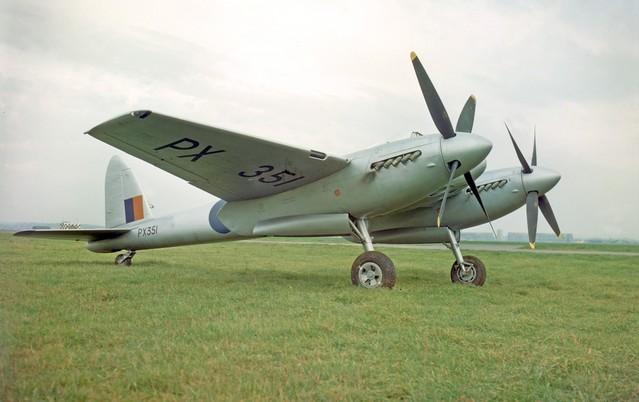
I've always been intrigued by the lines of this plane, sleek and muscular at the same time. While not used in great numbers due to the rapid pace of jet powerplant development it saw extensive use in the battle against communist forces in Malaya during the Malayan Emergency, also known as Operation Firedog. With it's useful payload and long range it saw service in this conflict from 1948 until 1955 when the last of these beautiful fighters were SOC and scrapped. Only bits and pieces of this once-proud bird remain, but David Collins of the UK has built a full scale nose/cockpit assembly and hopes to have a full fuselage built in the future. His book "DH Hornet & Sea Hornet" was used as the primary reference for this build, as well as his CA Sea Hornet build over on BritModeler. This book is very well researched and for the first time presents the first accurate dimensions and illustrations of the fastest twin-engine prop fighter of the post-war era.
When I was a kid growing up in Puerto Rico my dad brought home from one of his trips to Ohio a Profile Publications booklet on the DH Hornet. At about the same time a new (to me) modelling magazine called AirSpace Modeler featured an article on converting the Monogram Mosquito into the Hornet...put the 2 together and I was Hooked! Such a sexy looking airplane just begged to be built...but alas my skills were nowhere near what was needed to do it so I moved on...When CA announced that they were releasing a Hornet I was overjoyed and jumped right in to the build as soon as I got mine, but as most everybody else found out, it was a mixed bag, being a limited run injection molding, but with some excellent resin details. I built it OOB but corrected the landing gear angle, but somehow it didn't quite seem right...Then recently came the Trumpeter kit and I fully intended to build it but unfortunately this kit is waaaaayyyy off the mark, looking somewhat "Hornet-ish" which for me simply wasn't going to work, this bird has a very distinct look both on the ground and in the air. The issues with the Trumpy kit have been well-documented on other forums but I do believe that many of the issues stem from the fact that all of the existing drawings, plans and dimensions were wrong! The most obvious error is the shape and location of the windscreen: the lower panels are parallel to the canopy slide, not angled up from it as depicted in all the drawings that were currently available. This pushes the cockpit back from the nose which changes the profile of the kit. Fixing the many errors in the Trumpy kit was attempted over at Britmodeller but the issues proved to be not worth the effort, so back to square one...So I decided to go back to building the CA kit using some of the Trumpy detail parts to enhance the build. So off we go...
I broke down the build into areas that I intended to correct, as follows: Wings, nacelles and landing gear, fuselage and spinners.
Wings:
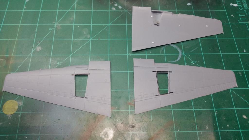
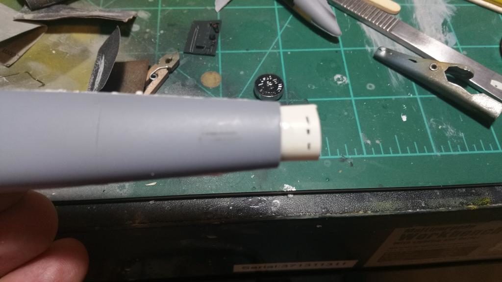
The first thing I found about the Hornet is that the landing gear bays were actually the underside of the upper wing, and that the landing gear is actually mounted to the main spar. So I prepped both wing undersides by carefully measuring and cutting the openings. The front spar is the double line in the forward third of the wing, the rear spar is the double line in the rear third. I taped the nacelles together in order to establish the lines to cut, then carefully removed the thick plastic with a sharp scalpel blade. Measure twice and cut repeatedly is the order of the day here...Before cementing the wing haves together I added a short length of Plastuct tube in the front wing opening, carefully checking the fit. The Hornet used an updraft carb on its Merlin engines, and while on the ground the engine air intake was a set of louvers on the underside of the wing just outboard of the engine nacelles. As the plane gained speed the tubes on the wing leading edge rotated open to increase the airflow. So while on the ground these tubes would be rolled closed. After getting the wing halves together along with the radiators I boxed the wells with sheet styrene and cut the oil reservoirs from the Trumpy kit and added a few boxes and wiring to busy up the inside.
After everything set up, I filled in most of the panel lines on the upper surfaces of each wing. All the drawings that have been published over the years show panel lines on the upper surfaces but in reality these drawings are portraying the locations of the internal ribbing! Like it's big brother the Mosquito, the Hornet upper wing was 1 piece of plywood with no paneling except where metal parts and fitting were attached. I used my favorite putty for this purpose, Miliput white fine epoxy. This stuff dries rock hard and sands to a feather edge. Next, I cut out the wingtip lights and epoxied the Trumpy lenses in place.
Now, using the plan views and pics in the D&V book, I reshaped the wingtips to a more accurate shape, as neither kit got them right. Ok, so far so good...but that was a lot of work!
Engine Nacelles:
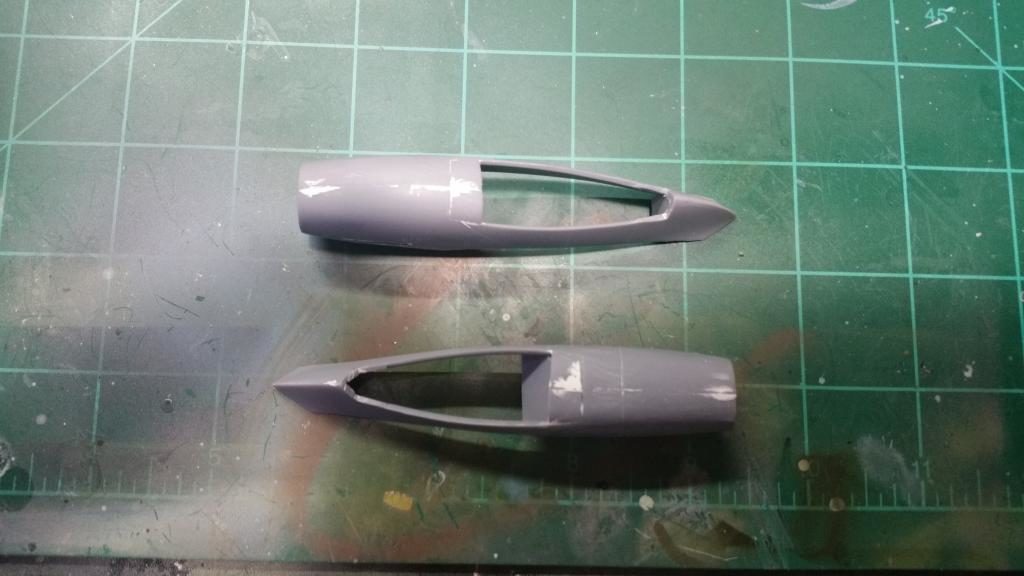
The biggest issue with the nacelles is the location of the landing gear opening; it's way too far forward! So after cementing the nacelles together, I took the gear door parts and cut the forward 6.5mm from each piece and cemented it to the front of the opening. After this set up I puttied and sanded to get a smooth opening, then cut the back of the opening 6.5mm further back. The back end of the nacelle is closed, so I used the pieces left over from the Trumpy nacelles to fill the back of the CA nacelles.
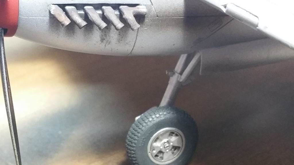
Next up, the exhausts. I had a set of leftover Moskit metal exhausts for Merlin engined a/c that I've had sitting around my spared box for 20 years or so...while not being exactly like the Hornet exhausts, they were the correct 5-port config and they looked So cool, being real metal, I used them and I am super-pleased with how they turned out!
The next detail item for each nacelle is I small tear-shaped bump on the forward starboard side of each nacelle, which likely made room for the starter for each engine. A glob of thick cyano wasn't gonna cut it...too hard to get a uniform shape for both engines. I wound up using a pair of leftover 1/32 position lights from a Hase Ki-84, which were the right shape and size.
Next was the nacelle bulkheads. I used the kit bulkheads detailed with a few items from the Trumpy kit and inserted at an angle per the real plane. Placement is critical here, if not placed properly you could shift the landing gear location! If you look on each side of each nacelle there is a scribed angle line, that line matches the angle that the forward bulkhead should be. The top pf the bulkhead should be just forward of the front of the scribed main spar location, so when you fit the gear in the forward part of the main gear sits right on top of the main spar. on the real a/c the bulkhead was angled to provide clearance for the Merlin supercharger and updraft conduit. I added some styrene stringers but later found they interfered with the gear fitment, so in hindsite, leave'em out until all the test fitting is done...
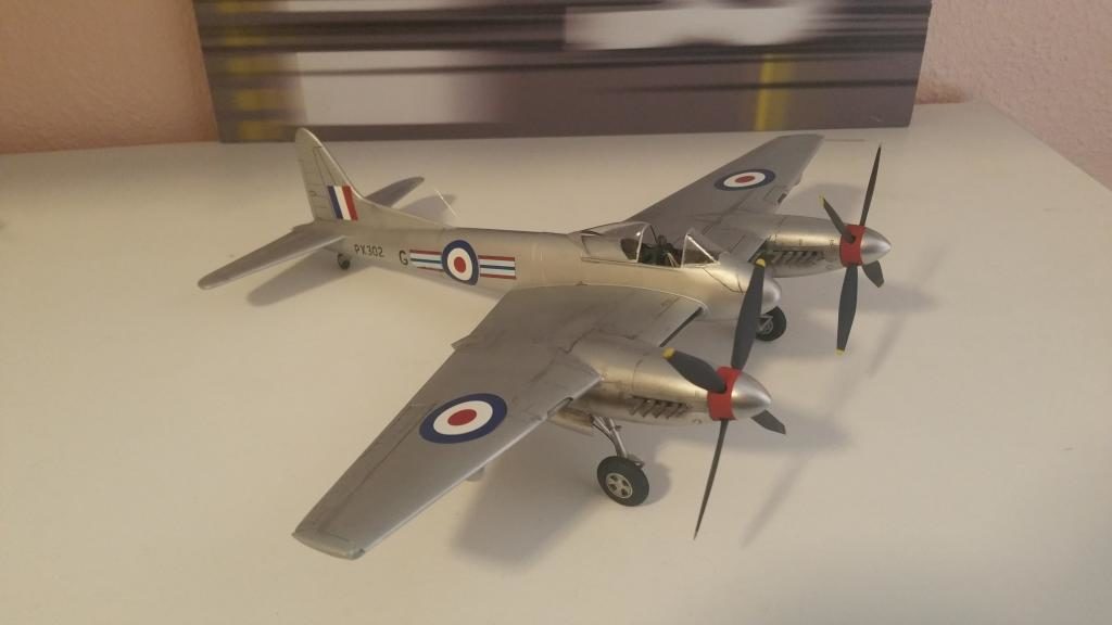
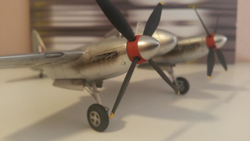
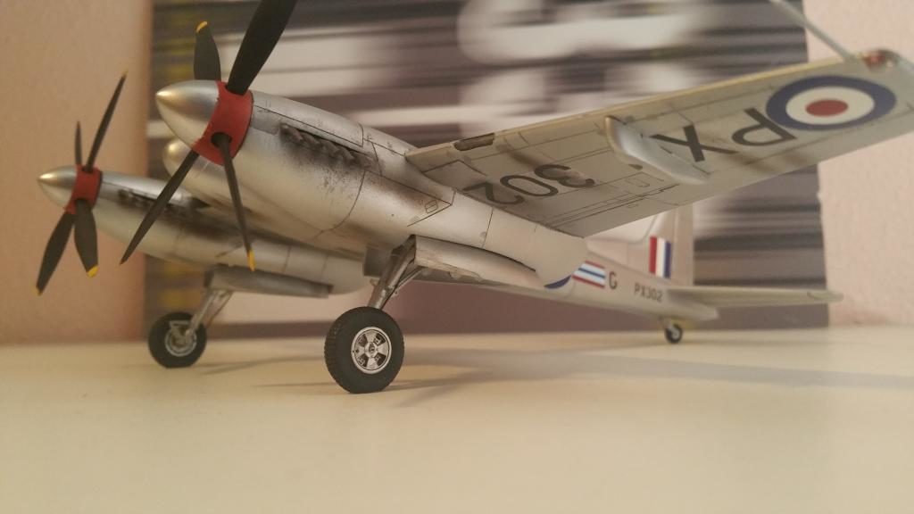
Finally, after looking at all the pics of the Hornet power egg, I was convinced the spinners were too shallow, on the real bird they look like big bullets; CA's effort just looked to short. So I went ahead and cut 2 circles of 20 thou styrene and added them to the back of each spinner and sanded them to shape. I had no intention of using the CA "props", they were basically just shapeless lumps of thick plastic and I didn't think I could get them to look consistent by sanding and shaping' so I took the easy way and used the Trumpy blades, shortened slightly. They may not be exactly right but look pretty close to my eye!


Landing Gear:
The gear provided in the CA kit is actually pretty accurate, albeit a little on the thick side. it's missing some of the cross supports and retraction pistons but is very usable as is. I carefully assembled each gear, be sure to make sure the gear is trued up as the cement sets. I cut off the wheel mounting pin and replaced it with brass rod for strength since I was going to use BarracudaDetails Hornet wheels instead of the kit resin wheels. These wheels are just amazing! You can see the the individual tread blocks and read the Dunlop trademark in !/48th scale!
To set the proper 14 degree angle for the gear rake, I made a simple gauge from a piece of stiff cardboard cut at 14 degrees from vertical. I had purposely not fixed the nacelles in place until I had the gear ready due to the very tight fit of the gear in the well. By moving the opening back the rear portion of the nacelle sides are too narrow for the gear to sit at the proper angle! So to fix that I removed about 1 mm from the rear crosspiece of each gear, and problem solved! Using the gauge I was able to fashion a set of spacers that would be cemented to the rear crossmember of each gear and insure that each gear had the same rake angle.
Finally I cemented the gears in their respective positions and fitted the nacelles in place. Now we're cooking!
Fuselage:
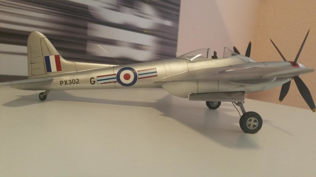
The lack of accurate dimensions meant that all the kits of the Hornet were an average too short. Because of the incorrect length just about all the Hornets I've seen built have a "stalky" look to them. Per the D&V book the fuselage length for the Hornet F3 is 35'2". Measuring the CA fuse with my trusty Murphy's Rule, it measures 32', which would require a 6mm extension to correct...hmmmmmmm...
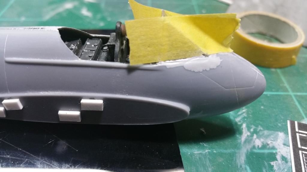
First I went ahead and assembled, painted and detailed the cockpit using Tamiya tire black with some drybrushing to bring out some details. I added a gunsight from an Eduard Spit 16 and used the Trumpy control column as it is actually very accurate. Once the fuse was assembled and set, came the moment of truth...where to cut, and how to fill, and keep everything squared up at the same time?
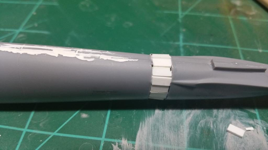
I chose to cut at the panel line just in front of the tailplane, where there shouldn't be a panel line anyway! Before cutting I made 4 light marks with a scalpel blade on either side of the cut. After cutting I took some thin styrene sheet and rolled it around a dowel to give it some curve and fitted it inside the front half of the fuselage and checked for the fit of the tail half. Once I was satisfied with how it all fit together I marked off the 6mm and glued the two pieces back together. Then I too some Plastruct strip and cut a series of short pieces to bridge the gap between the two halves. Once I had the gap completely filled with the strips and the cement had dried I used Miliput to cover the surgery. After sanding. I have a joint so strong I could use the fuselage as a bat and the joint won't give!
The Rest of the Story...
So the biggest issues I had with the kit have been dealt with; the rest of the build was pretty straightforward...hehe...
To fit the tailplane I drilled alignment holes and used brass rod for both strength and proper alignment. To fit the wings, instead of a spar I wound up using styrene blocks at the roots spaced so that the wing and the roots would match, that actually worked out well. I had some gaps as you would expect for a limited run kit, but I discovered what has become my second favorite gap filler; Vallejo's acrylic putty! Just squeeze along the gap thru the nozzle, take a wet finger or a damp q-tip and run along the gap and done! Because there is no shrinkage and it doesn't craze the plastic like most solvent-based fillers do there is very little finish prep involved. This worked great for the gap along the vertical stabilizer and the wings and nacelles.
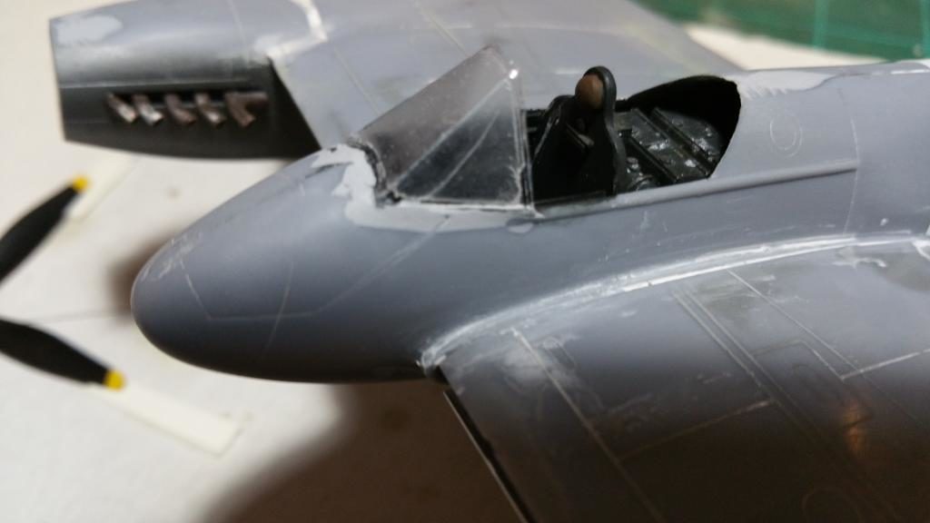
Next up was the canopy/windscreen...I learned a good modeling trick from my friend Rick Wilkes about cutting vacuform canopies...I poured plaster of paris into one of the two canopies, let it set and was able to get good cuts around the parts with not deformation or wrinkling. The canopy itself is a big letdown; It is the wrong shape and cloudy to boot. The Hornet sliding canopy has a very distinct shape at the rear, very much like an ink pen nib. So after dipping one canopy in future and separating the windscreen I carefully cut the edges of the canopy to match this nib shape. I then laid on some Parafilm and cut the frame to match the plans, and I am much happier with the result than the kit canopy.
Fitting the windscreen took a lot a very careful work, there are gaps all the way around the part. I used a lot of Mr. Dissolved Putty and Mr. Surfacer 500 to get the result I wanted. Take your time in this area.
Final details prior to paint include a pitot tube from Albion tubing and adding the air intake filter louvers to the underside of the wings. For that detail I photocopied the pe sheet from the HpH Hornet (oh Yes, I will build that one too!), reduced the copy and using rubber cement, attached it to some .005 styrene sheet, then cut in some louvers. It was the cemented in place and while not as fine as pe, it gives the appearance I was looking for.
Paint and Markings:
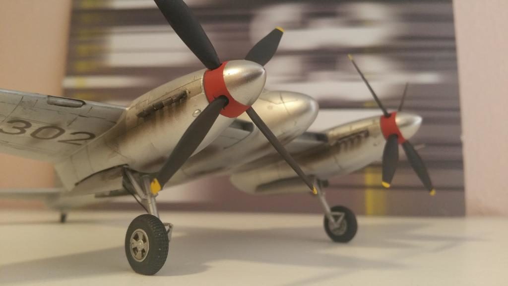
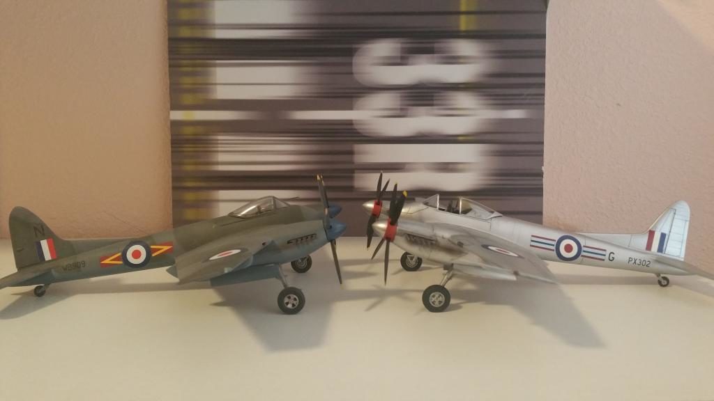
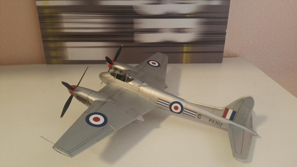
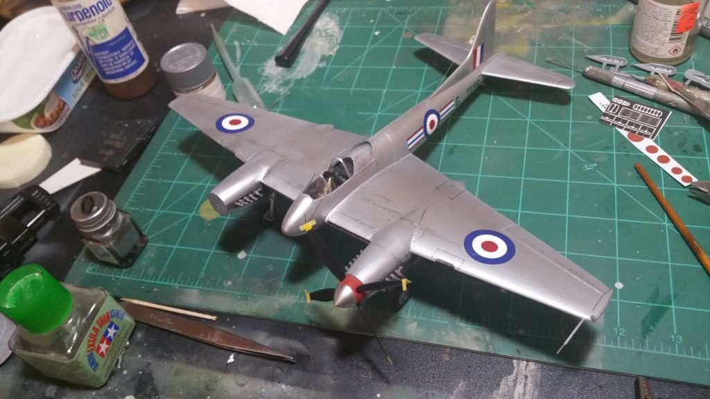
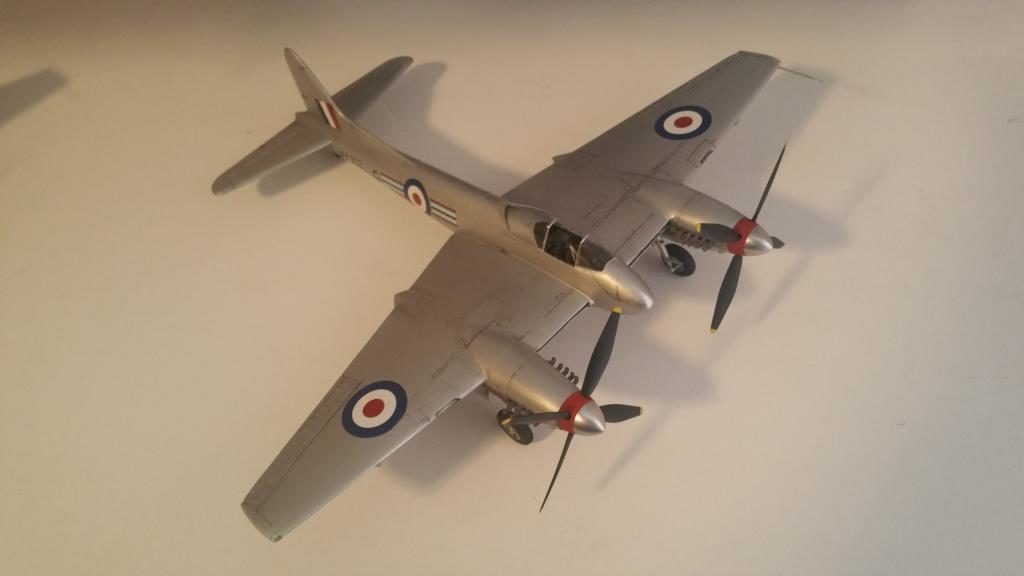
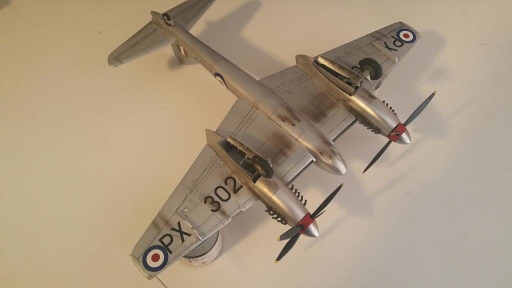
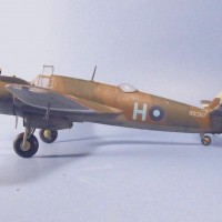
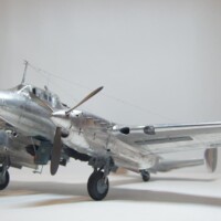
Hornets in the Far East were finished in one of two schemes: Dark Sea Gray/Dark Green/PRU blue or High Speed Silver. I chose a 33Sqn Hornet flying from Butterworth, Malaya in November of 1954. This bird was finished in High Speed Silver, which offered better airframe protection in the hot humid climate. 33 sqn. was heavily engaged in day-to-day bombing and strafing attacks and were pretty heavily weathered.
Before painting I sprayed on a coat of Mr. Surfacer 500 to check for flaws. I then applied a couple of light coats of Alclad HS Silver. I used Tamiya's black panel line accent color to enhance the few panel lines this plane has and I discovered that this stuff can also be used to tint silver to various shades...I used it to shade the panels that surround the exhaust pipes.
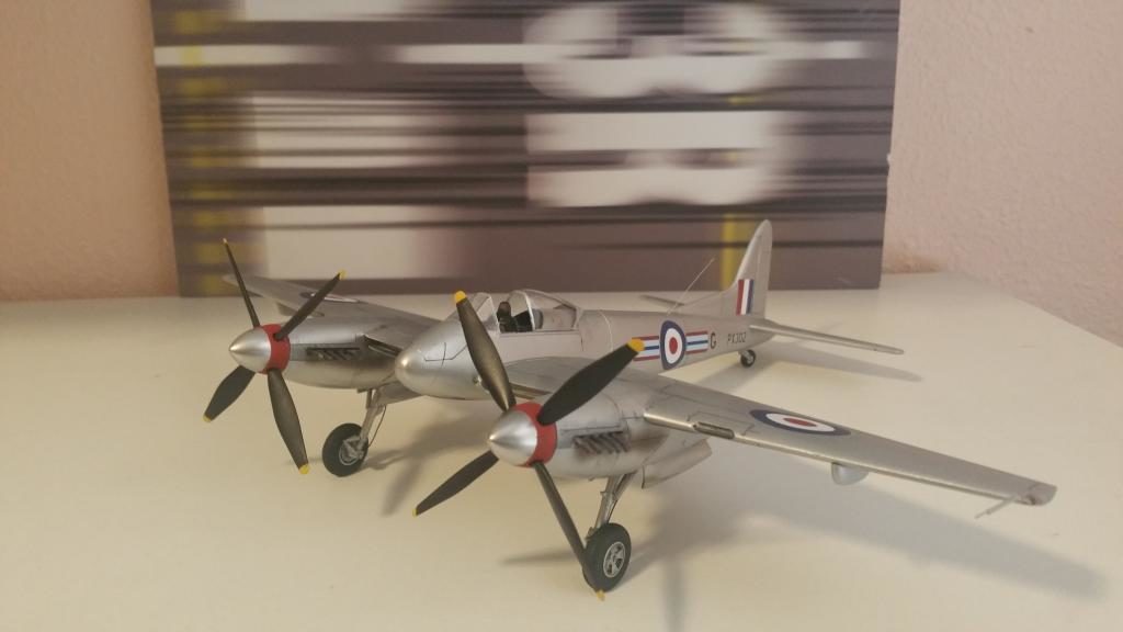
The decals I used came from Xtradecals Hornet/Sea Hornet Collection...and here is where my hard work almost came undone. You have to use the roundels from the CA kit in conjunction with the XD dull red centers, Easy, right? Well the CA roundels would fracture requiring multiple repairs, and the same thing with the XD decals, especially the Squadron markings. I managed to get everything sorta repaired but also found the decals did not adhere well either...After several days of unscrewing that I was able to get a couple of coats of Tamiya semi-gloss clear on, then add the exhaust and grime to finish up...Finally the Spinners! I sprayed them gloss black the Alclad Polished aluminum, sprayed the back half Tamiya Red and added the props...
FINISHED!
Well, at least until I get some decent looking RP's and 500lb bombs...
I am very happy with the result (besides the decal fiasco...) and now I have a Hornet that looks much more like the real Hornet I love so much,instead of a plane that looks "Hornet-ish"!


Outstanding build and tutorial, sir...and on an aircraft rarely seen done. Nice job!
Great attention to detail. Very good result!
Obviously a labour of love with a great result. I really enjoyed reading your extensive write-up but wish there were more pictures of the completed model.
There ya go! Thanx for the comments!
Very nice! Thanks for the detailed write-up as well.
Excellent build Juan, looking forward to seeing it next month at the Indy show.
Juan, she's a beauty, and you've got two of them! Just a lovely plane. Good old Sir Geoffrey Dehaviland! Beauty and function!
Beautiful build!
Nice Hornet..
Juan - outstanding! This is an interesting plane & you've done a great job. I see what you mean about the BarracudaDetails Hornet wheels! Very lifelike.
PS - I like the High Speed Silver, too.
Thanx, I appreciate the comment!
Looks good - too bad someone doesn't do this right, but I fear Trumpy has poisoned the well once again.
Without an existing airframe or accurate plans all a model company can do is fudge it. In Trumpeter's case they used the same incorrect plans from the Warpaint series that have constantly beenposted for decades, as evidenced by the way ybey rendered the landing gear struts. This doesn't excuse the poor execution of the kit, there is a huge amount of visual documentation for getting the basics right but accuracy has never stopped them from putting out a kit before...just look at all the RAF and FAA subjects they've already botched. I think someday once the accurate plans have been released we will see a better rendering but that's me hoping...(listening, Airfix?) Meanwhile I am gonna tackle the HPh kit...
Thank you for such an informative article Juan. Your attention to build accuracy is great to see & I will be saving your notes & pictures for when someone realises how popular an accurate Hornet would be. Your finished model looks superb. I agree with your suggestion to Airfix; I've already made one myself so I hope they are listening!
Thank you! I honestly think it will only be a matter of time, given the ambitious releases from Airfix of late.
Lots of work but your effort paid off, well done