Review: Trumpeter 1/32 F4U-1D Corsair
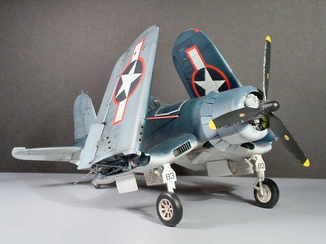
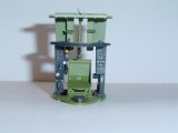
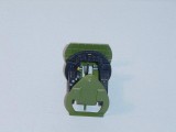
This is a re-post of an article I did many years ago, when I started writing "review" articles for a large, international modeling society, and before I became jaded with the entire process. Sadly, I cannot find but 2 photos of the completed project. Should I come across any others, I will add them into this article.
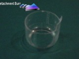
The kit features 355 pieces crisply molded in light gray plastic. If you've built any of Trumpeters' other kits, you're familiar with the moderate softness of the plastic. Easily correctable as far as molding flaws go, and easy to mess up if you're at the workbench when you should be in bed sleeping. These are presented on 9 gray sprues, and one clear sprue. The clear cowling (intended to display the VERY detailed Pratt-Whitney R-2800 engine) is packaged separately. Although not on a sprue itself, mine had a “separation burr” present. Also included are a fret of very nice photo-etched hinge pieces, 3 rubber tires, and a little bag of metal rods and 1 wire. These components are packaged in a separate box within the main box. More on the clear parts in a bit.
Upon initial inspection, the first thing that catches my eye is the detail. There's lots of it, and this should prove to be a challenging and fun build! The second thing that catches my eye is the abundance of ejector pin sink marks. This is the 2nd Trumpeter kit I've become involved with, and I'm curious as to why there are so many of them prevalent in their kits. Granted, I expect to work for my end results, but cleaning so many of these things seems redundant and non-productive at times. I'm about a quarter of the way through their 1/24 Bf 109-G6, and although the Corsair doesn't seem to have as many of them, they are in many of the most detailed areas.
The decal sheet included in the kit is a bit sparse. I thought perhaps there would be lots of stencils to add to the aircraft, but only a few are present with the major markings. The decals are brightly colored, and the register appears to be nearly perfect. Markings are for a restored aircraft belonging to the Confederate (Commemorative) Air Force and one from VMF-351, USS Cape Gloucester. I haven't decided what aircraft this will be modeled into, but I do have an unassembled Revell kit with Ira Kepfords' markings that I'm thinking about. There are other Corsair decals in this scale available on the aftermarket, and I'm guessing more will be available soon.
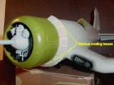
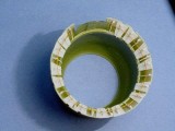
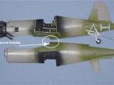
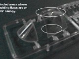
The clear sprue demonstrates a couple of molding flaws on the canopy in my kit. Two very distinct smudges, that appears to be in the mix… that is, not palpable on either side of the canopy, but “swirled” into the glass itself. Hopefully, a bath in the ol' Future will improve this. The clear cowling has a frosty appearance, containing many tiny “speckles” and streaks. More of an issue for those of you wishing to expose the entire engine, but I have a vial of Dark Sea Blue that should correct it nicely. The pictures of the clear parts do not show these flaws clearly, so I've outlined the affected areas.
The floorboard inaccuracies have been addressed in other forums, and yes…it's inaccurate. However, with a bit of cutting and some fairly simple scratch building, the cockpit can be made into a reasonable reproduction of the original.
The instruction booklet included with this kit is extremely comprehensive, yet easy to follow. Consisting of 20 pages, the diagrams are concise and include painting suggestions, as one would expect. The back cover has a simple yet nicely done decal location chart. The engine comprises 86 (!) pieces, not counting the wires I added myself to represent the ignition wiring harness. I'm sure that there a quite a few quarter scale kits out there that don't have a sum total of 86 parts, let alone in the engine….
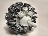
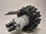
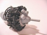
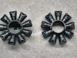
The 18 cylinder heads were airbrushed with Testors Model Master Acryl (which was used throughout this build, unless otherwise noted) Gloss Black, then dry brushed with Floquil Enamel Gunmetal. Actuator rods were brushed with the Gloss Black. I should note that all of the parts so far have cleaned up nicely, and there is NO flash noted anywhere. Some of the paint color callouts do not match those of my references, so I went with what my photos depict. The front crankcase housing, including the magnetos and electrical harness, were painted in Gray Primer, which to me is a closer shade to Light Gray than what is labeled as such….seems like the light grays I have are a bit anemic. The rear portion of the engine block is a bit sparse, with no carburetor assembly or supercharger intake. These could be scratch built by someone wishing to utilize the kits' clear cowling, but otherwise will be virtually invisible. The distributor caps were painted gloss black, and the intercooler plates bronze-gold.
Once the major components of the engine were painted and assembled, the exhaust outlets were painted with Burnt Iron lacquer. A problem I encountered during test fittings of the cylinder banks and exhausts was that several of the “pipes” from part G13 fell about 1/16” short of the rear side of the front cylinder heads. This was easily remedied by light sanding of the mating surfaces of the 2 cylinder bank assemblies (parts G1 and G3). The exhaust collection ring now went together nicely, and the 2000 HP power plant was quickly taking shape! The next step, and for me the most time consuming, was the assembly of the rocker covers? atop each of the 18 cylinder heads. Each of these consists of three parts, making up 54 of the engines parts. Trumpeter does not include any type of ignition harness wiring, as the movable control surface hinges are the only photo-etched parts included with the kit. The engine will look a bit bare without it, so I decided to add them using 0.015 diameter solder. I picked up a 1-ounce roll at Radio Shack for about $4.50. Using a # 72 bit in a pin vise, I drilled out two holes in the electrical harness ring in front of each respective cylinder, then two holes in each corresponding cylinder. I snipped off small lengths of the solder, and used tiny drops of cyanoacrylate to secure them in the drilled holes. There are 2 stubby beginnings of these wires molded on the ring in front of each cylinder, and I tried to hide them behind the solder “wires”. The results were not 100% accurate, but I'm happy with it and the engine looks “complete”. Once I was happy with everything, I sprayed a light coat of Future over the front and rear of the engine, and applied a black oil wash to bring out some of the details when it was dry. This was again covered with Testors Flat Acryl, and then I dry brushed the bolts and such with the Floquil Gunmetal.
One of the only points of contention with this kit, as has been discussed a great deal already in numerous circles, is the cockpit floor. Namely, it has one, and the Corsairs actually did not. This is easily correctable, and this will be the primary focus of this chapter.
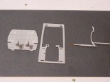
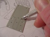
After test fitting the firewall, foot pedal supports, instrument panel, and back wall of the cockpit, a line was drawn around the perimeter of the “floor” (Piece A15). This ensured that the location holes for each of these pieces weren't compromised, and gave an idea of how much supporting structure would be needed to remain. Turns out, not much. As you can see from the pictures, most of the flooring was cut away, with ample space left to hold the pieces together to form the “office” in a barely noticeable manner. A scribing tool was used to trace along the drawn on lines, progressively deepening with each pass, until it was nearly scribed completely through. Once thin enough, a sharp #11 blade finished the separation, and all rough edges were filed and sanded smooth.
Since removing the floorboard does remove the locating surface for the control stick/control surface linkage (piece F21), a small hole was drilled into the forward end of it with a pin vise bit, with a corresponding locator hole in the firewall. A thin piece of copper wire was superglued into the piece, and then to the firewall. The result will be a control linkage that accurately spans the open void beneath the pilot's seat, and the small wire allows for adjustment of its position prior to cementing. The rest of the cockpit was assembled according to the kit's instructions; Again, an acetate instrument dial set is provided, which in this scale looks great. The open floor provides an excellent view of the completely bare fuselage you weren't supposed to see. I cut several lengths of thin styrene rod (0.047 diameter) and cemented them where the fuselage ribs should be. This process will be repeated along the inner surface of the main wing section as well, when the time comes.
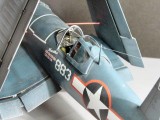
The cockpit was detailed using photos I took of the Goodyear FG-1D Corsair at the Kalamazoo Aviation History Museum (Air Zoo). Granted, it's not the exact same aircraft, but it's a very close approximation. The upper half of the walls were painted Aircraft interior black, with the areas below the side instrument panels being Interior Green. I added a photoetch seat harness from a 1/32 Wildcat detail set I have for the old Revell F4F-4 kit, so now I need to get some more seatbelts…one for that great old kit, and one for the new Trumpeter Wildcat I just picked up! I understand the new P-40 kit about to be released has some PE buckles at least, so Trumpeter seems to be picking up on the modelers' wants and needs.
The tail wheel/hook assembly is next, with very few attachment points cemented; it is largely held together by friction, as it is designed to be retractable. I'm not exactly sure why Trumpeter has engineered this feature, as the main gear legs are not retractable. It is very detailed however. I've decided to leave mine in the movable state until construction is complete…. if it supports the weight of the model, so be it. If not, I'll secure it with Tenax. The black stripes were added using thin strips of plain black decal. The rudder goes together easily, and is secured to the tailfin via a photoetch hinge and rod.
Securing the engine, cockpit, and tail wheel assemblies to the right fuselage is next, followed by putting the fuselage halves together. The fit here is excellent, with all assemblies perfectly flush. So far, the kit is progressing well with assembly being very enjoyable. Lots of opportunity to add as much or as little detail as one may see fit, and a simple floor correction to improve overall accuracy. And, a small sense of accomplishment as each step is complete and the Corsair begins taking shape!
I pirated (it's a Corsair, what else would I do?) the canopy from an old Revell kit I had on “the pile”, as it has the 2 “correct” horizontal frames, while the Trumpeter one has the frameless canopy found on later –1Ds (F4U-1Ds starting with Bu. Number 57583 and beyond had frameless canopies). My plan was originally to paint the tri-color camouflage scheme, which was not applied to the –1D variants, so the changes incurred were due to this. . I think some actually did leave the factory in those colors, but fleet regulations had them overall Sea Blue in a hurry. I also filled in and sanded smooth the under-wing mounting holes for zero-length 5” rocket pylons, as well as the cutout step on the starboard, inboard aerilon. These were not production-standard on the –1As, and were found on the later model –1Ds and –4s. The 13' 4” Hamilton-Standard propeller found on the earlier Corsairs will be pirated (!) from a 1/32 scale Hellcat lying forlornly on said pile, as the –1D props were 13'1”. The starboard wing of the kit has a recognition light molded into it in the appropriate spot for a –1A, so that was a bit of drilling saved. Had I proceeded with a late model –1D (after Bu. # 57484), this would've needed to be filled. Hey, remember that “molding flaw” I talked about on the canopy in the 1st installment? It disappeared with a 2-coat Future bath. One less thing to deal with!
The Corsair has 4 ailerons on each wing, and in now-standard Trumpeter fashion, they were all hinged, so as to be movable. Not that I don't like working with PE. I quite enjoy it. But, my goal was to build this kit according to the instructions, with detailing added here and there, but without omissions. So it sat. And sat. A regular Sitzkreig. Anyways, once I got back into it last week, it actually progressed fairly well, until it was time to have the hinges work together as they should.
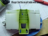
The gun bays build up nicely, and are detailed to a fair degree. Again, the superdetailer has room to make it as complex as desired, but the bays were unlikely to be opened with the wings in the folded position. Did I mention that you'd pretty much have to display your Corsair with the wings folded, unless major structural revisions are undertaken? More on that later. The bays were painted Interior Green (I'm out of Yellow Zinc Chromate, they'll be closed, and I was putting my head down and getting through this series of steps) and the .50 cals painted Burnt Metal. The gun barrels, which can be visible if someone with a flashlight were to peer into the openings in the wings, don't need drilled out. Trumpeter molds them with recessed tips, to simulate a hollow barrel. Care must be taken, however, to align them properly. The shell-ejector chutes will need drilled out though, as they are visible from the bottom of the wings. The wings themselves required a bit of sanding after the top and bottoms were secured, as the edges fore and aft do not match up exactly. Not a huge mismatch, but one that will require correction.
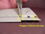
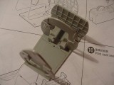
Now, the hinges. They assemble without too much trouble individually, but they do take some time and concentration. On page 10, Step 17, part number D23 is incorrectly labeled as D26. This (D26) is for a right inboard aerilon, not the outboard flap as depicted. If it is separated from the sprue at this point, it can misplaced. I labeled mine “D26” in pencil, and stuck it in the little PE/rod/tire box until needed. The “shaft” of each is a Æ0.8 wire, which the instructions would have you create a flange at the ends to hold each hinge joint in place.
I spent about 3 days, off and on, connecting each of the hinges according to the “book”. I found that what worked best for me was this: threading the whole wire through one end of hinge joint, until the end just peeked through then snipping it, followed by a firm crimping of each end simultaneously with needle nose pliers. Sounds easy, and it wasn't written like this because I think I have a new modeling technique to break ground with, but when you get to this part of the build, you'll see why it's outlined so. Granted, a large majority of the frustration experienced here was most likely due to my own skill level, and many of you will probably not have these troubles, but be forewarned that this process is a pain. Also note that the photos of this step were done after the completed hinges were assembled with the wings, and the actual crimping/flanging was done well before this time. The photos I took then were blurry, as was my mentation, so I “re-enacted” the step. Ironically, it went slightly smoother this time! One suggestion to Trumpeter; include a few extra PE hinges on future frets, please. There's not any carpet around my workbench, but boy, do these things disappear into plain site easily!
There were obvious discrepancies in quality between sprues “C” and “D” that I experienced during this build...the differences in quality are embarrassing. Sprue “C” is full of ejector pin marks (only in the highest visibility areas, though), while “D” didn't have any. I freely admit to a very limited knowledge of the actual molding/manufacturing end of this wonderful hobby, but still…you know what they say about sprues molded on a Friday or a Monday.
Now, after a short-lived victory, the time came to join them together. I will hand it to Trumpeter for the engineering of these features. They do fit well, and for a plastic model airplane, are kind of complex. However, the most inboard attachment point for the aerilons is tricky. Apparently, it is a stress point for torque occurring with flap movement, as I superglued this in place initially with slow CA, only to have it easily separate upon testing the hinge. Another application of CA, and the last of my patience, before I mixed up a small dose of 5-minute epoxy to secure the darned thing once and for all. All the other hinges received a reinforcing spackle of epoxy as well.
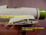
I have to admit; I did feel a small sense of actual accomplishment after these steps were behind me. The wing fold mechanisms were up next, and assembled easily. Nicely detailed and accurate, I will probably drill out a hole or two and stick some wires/hydraulic hoses into them to finish off the panels.
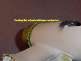
The inside of the fixed wing assembly had some plastic rods added to simulate fuselage ribbing, as a small area of this is visible though the floorless cockpit. One of them ended up a bit skewed, in relation to the others, but it's not one of the ones that are visible beneath the foot troughs. The whole assembly was then sprayed Interior Green. The color callouts are, in many instances, wrong.The engine cowling and cowl flaps are 2 separate pieces, and these were joined. The flaps themselves are notably inaccurate; primarily because approximately half of them do not exist. I wish I'd photographed the unassembled piece, but I was on a roll now and just didn't think of until it was too late. You can see, however, the additional flaps scratch built from sheet styrene, and see how many there weren't. It's not 100% accurate, but it is a huge improvement. I also scratch built the cowling flap actuators and linkage mechanism from Evergreen sheet and rod styrene, using fine copper wire for the linkage. I think this adds a nice level of detail to the assembly, and in this scale, is almost necessary
The canopy and windscreen are ready for masking and attachment, and painting should commence today or tomorrow. I forgot to mention, now that the –1D is a –1A, whose plane is it going to be? Well, having served in VF-84 (“We're the Jolly Rogers…Who the Hell are you?”) my 1st inclination was to do one of the VF-17 birds. However, I have seen a high amount of those lately, and although I love'em, another Blackburn/Kepford mount can most likely wait awhile longer, no disrespect intended. Instead, I've decided to depict another famous, and often-modeled Corsair…that of Pacific Theatre ace/hero/infamous personality MAJ Gregory “Pappy” Boyington, USMC.
From September 1943 to January 1944, a period of only 83 days, the Empire of the Rising Sun suffered damage and destruction of incredible veracity; 197 planes destroyed or damaged, supply ships and troop transport barges sunk, and ground installations rendered useless. The work of a concerted Allied operation, or a major offensive launched against Japanese forces to take control of “The Slot”? Negative. This amassed carnage was the work of just 25 men doing their job. 25 pilots who, under the command of their squadron CO, wreaked havoc upon the Imperial Japanese Army and Navy like no other squadron during World War II. Who were these men, and who was their leader? Marine Fighter Squadron 214 (VMF-214), led by MAJ Gregory “Pappy” Boyington; The Black Sheep Squadron.
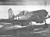
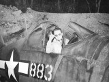
As no one in the squadron (or many other squadrons) had their “own” plane, the pilots flew whatever ones ran. One aircraft was used, however, frequently by Boyington and his regular wingman, 1LT Robert McClurg (7 kills). The plane, Bu.No. 17883, was nicknamed “Martha”. The aircraft used in the squadron's “Baseball Cap” photo is the –883 plane as well. Interestingly, the plane most associated with “Pappy” is Bu.No. 18086, or “LucyBelle”. This aircraft was used for a photo-publicity stunt arranged by the Press Corps after Boyington's 20th kill, to boost morale on the home front. He essentially sat in the cockpit while press photographers slapped some phony kill flags on the fuselage (and in their haste put some on backwards) and took some shots. Pappy spent all of about 20 minutes in this particular plane, none of them in combat. "LucyBelle" was believed to be in reference to Boyington's mistress, Lucy Malcolmson. Entrusted with $15,000 of his money, Ms. Malcolmson took the high road, leaving Pappy with less than fond memories of her. He went on, referring to the plane as “LuLuBelle” in the future, because, as historian Bruce Gamble puts it, "He had about fifteen thousand reasons to forget Lucy, each one worth a dollar."
Basically, all that was left at this point was the completion of the undercarriage, and some small detail parts. The main landing gear struts were riddled with the ejector pin marks now so familiar, and were filled with Squadron White Putty and sanded. The oleo strut scissors linkage appears to be a bit large for scale, but at this point I was not doing any more major (or minor, for that matter) modifications. I did, however, wish to dress the legs up a bit, and added some 0.015 solder wires to replicate hydraulics and brake lines.I mentioned earlier that the wing fold mechanisms were nicely detailed, and they are; they compare very favorably to photos in Detail & Scale, save for a few small omissions corrected easily with plastic rod. The fine solder worked well here as hydraulic lines too, but when assembled in the folded position, something more was needed for support. The kits' supplied hinge and lock mechanism is too flimsy to support the upwardly folded Corsair wings, and they list at an inaccurate canter. I corrected this by securing a third “hydraulic” hose in the center of either wing fold, which was actually a heavy-gauge copper wire strand. Held in place by 5-minute epoxy, these support braces work well to securely fasten the folded wings in the correct position. Yet they are small enough in diameter to be easily disguised as normal “plumbing”. If one chooses to display this aircraft with the wings down, some major reworking is called for, as they kit as supplied does not possess this capability. The resultant gap between the wing's components is huge.
The 2-piece spinner supplied in Trumpeter's kit is tepid in detail, so the entire prop was replaced with the one from Hasegawa's 1/32 Hellcat kit. More accurate spinner, and about 1.5mm longer, which scales out a little closer (ballpark) to the larger prop on the –1A Corsairs (about 7” longer than the –1D props). Painting consisted of a primer coat of “Primer Grey” Model Master Acryl, followed by Flat Black pre-shading. The Tri-Color camouflage scheme was carried out in Flat White, Intermediate Blue, and Dark Sea Blue. Panel fading on the upper and side surfaces was done with the same colors, lightened with a bit of Flat White. I don't know the ratios or proportions, I just mix it up until it “looks right”; real scientific! Final weathering consisted of dusting with light blue and white pastel artists' chalk. I will never do this again…to this day, the aircraft is vulnerable to fingerprinting, and is generally just a hassle to deal with. Live and learn. The numerous paint chips and dings, prevalent among Pacific Theatre planes living on crushed coral runways, was replicated with Aluminum Metalizer and a very small, pointy brush.
All in all, a very satisfying build. It presented numerous challenges, and enhanced my overall skills by forcing me to do some things I was not previously comfortable with. Trumpeter should be commended for producing the large-scaled, accurate kits that they are becoming famous for; a few inaccuracies here and there, as with most any kit, but really nice stuff overall.
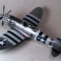
great bird, and very informative. sure hope you can find more pics of the completed project.
James,
I believe this would be the first full kit review here at iModeler. Thank you so much for sharing it, hopefully we'll see more of these soon (everyone please feel encouraged)!
You're very welcome! The Hellcat article I submitted yesterday is similar. 🙂
James agree with editor, this is the only one I nave seen that did cover some actual modeling steps with a "how" you did it. No ACE or revit counting and / or too much opinion(s) on foot notes of history that are just stories said so many times it then becomes another different story. I tried once myself for longer detail build on here but it failed so I took it off because I had the impression that with the "just post a picture" and run was the normal thing to do. with your nice model ( yes even Trumperter), and a how to, models can be built without the "paste and paint" Timagas etc. see, effort does pay off without someone telling you they might be 1 or 2 Milm to long / short... to many this and that... and thiese folks do not build, just advise... thanks for the article.. WS
Well, thank you C. Wayne! I'm happy that my articles are being well-received here on iModeler. Hopefully, people can learn from my mistakes...:)
Additionally, I build for me. I never was a "rivet counter", and as long as a replica looks like it's intended subject, then I'm happy. That's what's so great about our hobby - some people derive their happiness by striving for accuracy, others, like me, just have fun building and painting.
A fine example of the Corsair I must say...very nice indeed. And the read was terrific - thanks for taking the time to compose such a detailed background article.
Actually, if you haven't changed the prop, the Hellcat prop is likely correct. VF-17 replaced their props with Hellcat props when they got to Bougainville because the shorter props didn't stir up so much coral dust while on the ground - taking off, landing, taxying, etc., and they improved performance (which is why the F4U-1D went with that prop from the factory). Most other units in the Solomons eventually did the same thing.
Nice model from a kit that - as you demonstrated - "needs extra effort."
THIS ARTICLE I HAVE GOT to show Dad ! I imagine it would bring back a LOT of memories ! my compliments on a GREAT job .. and patience ! He didn't talk too much of the "problems" "over there" at the dirt strips, BUT he loves real articles about those times ! for you to go into such details, is remarkable ! PROUD to be an amateur modeler,AND see such detailed work done, with sometimes scraps, pieces,etc.