Work In Progress: 1/32 Trumpeter F6F-5 Fleet Air Arm Version
This article is part of a series:
It's been a while since I have posted an article; I was getting the shakes so decided to do a work-in-progress piece. This is my latest commissioned build started 10/1/18. It is the 1/32 Trumpeter Grumman F6F-5 Hellcat but will be finished in British Royal Navy Fleet Air Arm (FAA) Camouflage.
Brief Kit Overview:
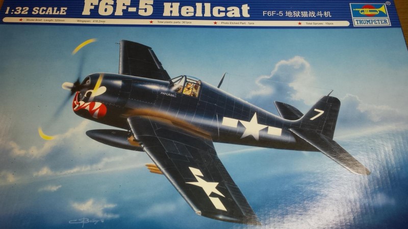
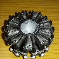
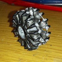
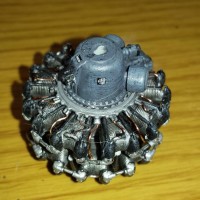
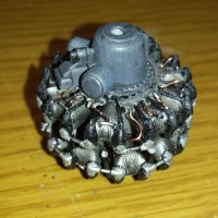
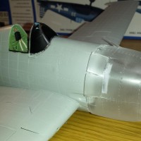
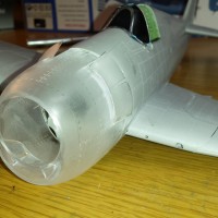
This is one of Trumpeter's older kits relative to the companies history. I have built a lot of the newer Trumpeter kits lately and you can definitely notice the difference verses the latest kits. Despite these differences this kit features the usual well rendered surface-details I have grown to love. Overall this kit has exceptional detail especially in the cockpit, engine areas, and within the fuselage. The landing gear and gear wells are nicely detailed and robust, but does lack brake lines. I will be adding those with lead wires. Regarding details the kit has most of the machinery and engine mounts behind the engine, including an outstanding detailed engine and exhaust manifold arrangement. You need to supply your own ignition wires. It also contains a vast amount of radio and electronic gear located in the fuselage section immediately behind the cockpit area. Unfortunately none of this detail can be seen unless you modify the kit such as opening several access panels. The kit also contains parts for all 6 .50cal machine guns and does have removable wing panels to display this area. The clear pieces look great and do fit well. The IP is provided as a clear piece which I do not like because you must then mask the individual instrument dials which is time-consuming and challenging. I used a mask set to accomplish this. Showing its age the kit does have some flash, and some of the small, finer moldings are defective, but nothing major. This is all fixable. I am not crazy about the clear 1-piece cowling piece but it fits well and is easy to install and remove if desired. I just dont like working with clear plastic fuselage sections. This kit also comes with a small PE sheet. This brass sheet includes what looks to be seat belts but I have never seen seat belts like those included. They are incomplete. I therefore purchased the outstanding Eduard "Steel" series PE painted seat belts designed for the F4U Corsair. The worst part of this kit is the poor design of the wing fold break separating the inner wing section from the outer sections. The design is fine if you use the wing fold options and is well detailed to do this. The problem exists when you build the model with the wings in the extended position. The joint is horrible. It is flimsy with very little surface area to glue and reinforce these 2-primary structures. I needed to use plastic strips within the wheel wells to reinforce the wing otherwise it would just break and fold on itself. This also makes it very tricky to align the inner and outer wing sections on the wing surface at the break. You may want to devise another method to fix this issue because my method changes the internal look of the wheel wells.
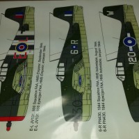
The decals look great and complete but I will not be using any of them. I have purchased the Techmod FAA Decal set for the Grumman Mk.I version. Unfortunately this version of the Hellcat, F6F-5, is not the Mark I. To be accurate you would need the F6F-3 Variant of the Hellcat. Oh well...close enough for Government work...LOL! I will be using the decals for an aircraft assigned to the HMS Indomitable from 1944.
Brief Construction Summary:
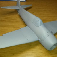
This model built up much faster then my usual builds of this size, and complexity. Overall the fit was average to above average. The primary reason for the quick build is because I decided to eliminate all unnecessary detail and structures. If you cannot see it I eliminated it. This leaves a lot of parts for the spares box. I also only assembled and detailed the front of the engine. As already mentioned the primary challenge was the wing-fold joints. Terrible design!
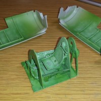
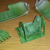
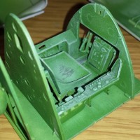
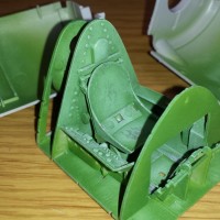
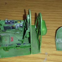
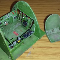
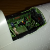
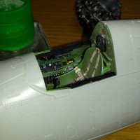
The construction process is traditional with everything starting in the cockpit area. This area builds up quickly and is well designed. It fits very well into the fuselage halves. The most complex section in this area is the gun-sight assembly. It is small and very fiddly. I added some cockpit placards and dial decals to busy up the cockpit. I also needed to add the gun-charging handles but the kit includes some decals to help with this area but not pointed out in the instructions. The other most complex and fiddly area is the complex tail-wheel assembly. It must be completed and attached prior to closing the fuselage. The instructions are not the best related to this section and I had a few trial and error attempts. Another design problem with this kit is the pilot's head rest. It is molded into the rear bulkhead and this is fine, but it is molded much to low. Once the cockpit is assembled the head rest is almost directly behind the pilots seat and the top of seat touches the bottom of the head rest. All my references show this headrest much higher on the bulkhead. The fuselage was closed at this point and if you assured everything was aligned it closed perfectly. I needed to use a lot of pressure to insure the rear fuselage area directly behind the cockpit rear bulkhead conformed to the shape of the bulkhead and eliminated any gaps. The engine has a lot of detail and therefore pieces. I completed this section and left off the rear details not seen through the cowling. The engines complex exhaust and manifold area is presented well but looks like a nightmare to complete. It will not be seen so I am leaving off the exhaust section of this assembly. The intake assembly which attaches to the rear of all the cylinders does not fit correctly and I need to modify the pipes in order to get this large assembly to attach to rear of engine. You cannot leave this section off because it is what mounts to the firewall and holds the whole engine assembly in place. I choose not to attach the motor at this point in order to ease painting. If you attach all of the engine pieces to the rear of engine you must attach the engine prior to closing the fuselage. It will not fit after the fuselage is closed up! Glad I did not need to do this.
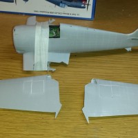
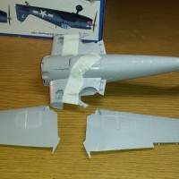
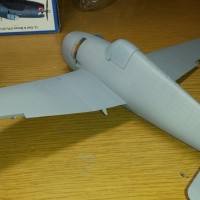
The flying surfaces and control surfaces were all assembled with no issues noted and aligned well once installed. The wing center section was assembled and the wheel wells built up and inserted into this area. The wheel well assembly was a little tricky and fiddly. This whole center wing assembly with bottom fuselage section fit into the completed fuselage perfectly with no noted gaps except directly behind the lower cowling section forward of the wing leading edge. These parts did not align perfectly but is easily fixed with some quick sanding on both sides of the fuselage.
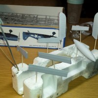
I left off all the control surfaces for painting. The center drop tank is nicely detailed and assembled perfectly. No gaps or filler needed. I primed all the parts and now it is ready for painting. Let the fun began. The primary colors that will be used are: Dark Slate Grey, Dark Sea Grey, and Sky. It is important to note that many model references suggest using Olive Drab in place of the Dark-Sea Grey. Although the final colors may have similar characteristics all my better references note that Olive-Drab is not used by the FAA during this time period. Stay tuned for the completed build.
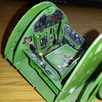
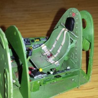
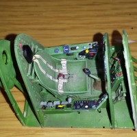
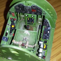
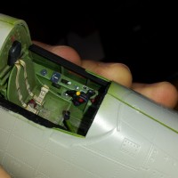
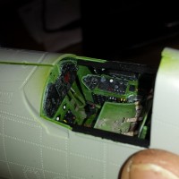
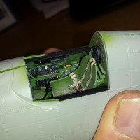
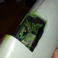
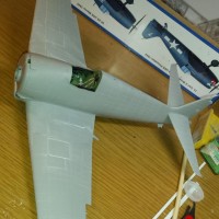
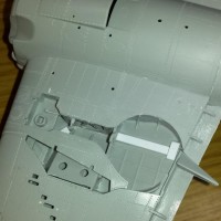
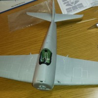
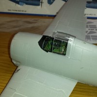
Coming along nicely, Paul...
Looks GREAT so far, Paul. Plenty of details you can see. It's too bad the -3 glass behind the pilot isn't there on this Trumpy model. Then you could see a few more details behind the pilot's "office."
Paul, that cockpit is admirable, very detailed, so much it pops out with your fine highlight. I also like the way you reproduced a weary cockpit green, it just looks the part.
That clear cowling is odd, but I guess some people might enjoy having a “window” and expose some of the engine details without the need to cut plastic.
Lovely build, Paul, I’ll definitely be along for the ride. Great office work and love the P&W.
Looking good!
Very nice